03/19/20
Message Overview:
Fault Message:
APU GEN FIELD -VE TO GROUND FAULT
Fault Code:
2420102LPS
Associated CAS:
| Reporting LRU: | Auxiliary Power Unit Generator Control Unit (APU GCU) |
| System Description: | 24-22-00 |
| Schematic Diagram: | 24-22-00 [ Global Express ] [ G5000 ] [ Global XRS ] |
| Wiring Diagram: | 24-22-01 [ Global Express ] [ G5000 ] [ Global XRS ] |
Fault Description:
The Auxiliary Power Unit Generator Control Unit (APU GCU) has detected a failure with the field negative to ground circuit and consequently resulting in Auxiliary Power Unit (APU) Generator to tripped off-line or not come on-line. Inhibited during Take-off and Landing.
Possible Causes:
- Auxiliary Power Unit (APU) Generator (A110)
- Auxiliary Power Unit Generator Control Unit (APU GCU) (A109)
- Associated Wiring
Troubleshooting Tips:
Advisory Wire/Service Bulletin: None
Forum Articles/Infoservice/Newsletter: None
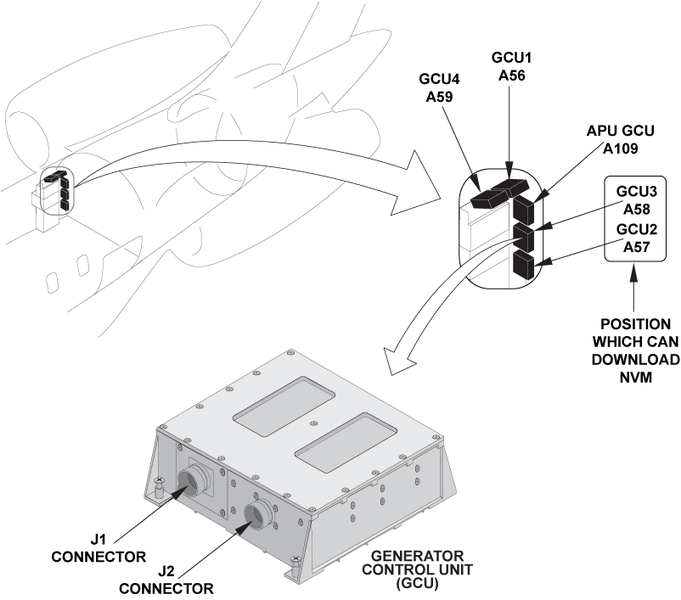
NOTE: A GCU patch cable (GSE REF # 24X-24-02) can be used to swap the GCU 1, the GCU 4 and the APU GCU into position 2 or 3 (for troubleshooting only). You can monitor the GCU fault in CAIMS via the active faults page. The GCU NVMs can only be downloaded at position #2 or #3.
Quick Links:
| Removal of the APU Generator | AMM 24-22-01-000-801 [ Global Express ] [ G5000 ] [ Global XRS ] |
| Installation of the APU Generator | AMM 24-22-01-400-801 [ Global Express ] [ G5000 ] [ Global XRS ] |
| Removal of the Generator Control Units (GCU) | AMM 24-24-01-000-801 [ Global Express ] [ G5000 ] [ Global XRS ] |
| Installation of the Generator Control Units (GCU) | AMM 24-24-01-400-801 [ Global Express ] [ G5000 ] [ Global XRS ] |
| Wire Repair - Maintenance Practices - ALL | SPM 20-12-10-02 [ Global Express ] [ G5000 ] [ Global XRS ] |
Troubleshooting Recommendations:
- Swap the APU GCU with the GCU#2 (physically or using the GCU patch cable). Is the fault still present?
- If YES, continue with next step.
- If NO, replace APU GCU and do close out.
- Disconnect connector A109P1 (APU GCU) and A110P1 (APU GEN).
- Perform a wiring check as follows:
From To Result A110P1-B Ground - If wiring defects are found, repair defective wiring as required and do close out.
- If no defects are found, continue with next step.
- Replace the APU Generator.
- Do close out.