12/17/25
Message Overview:
Message Name:
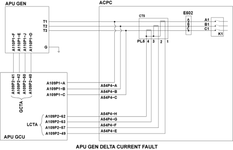
APU GEN [DIFF PROTECTION FEEDER]
Message Code:
2420124LPS
Associated CAS:
| Reporting LRU: | Auxiliary Power Unit (APU) Generator |
| System Description: | 24-22-00 - Auxiliary Ac Power Supply |
| Schematic Diagram: | [ Global Express ] [ G5000 ] [ Global XRS ] SSM 24-22-00-101 - Auxiliary AC Power Supply System - Electrical Schematic |
| Wiring Diagram: | [ Global Express ] [ G5000 ] [ Global XRS ] WM 24-22-01 Auxiliary AC Power Generation System - Global Express 9004-9010, G5000 - ALL, Global XRS - ALL [ Global Express ] [ G5000 ] [ Global XRS ] WM 24-22-01 Auxiliary AC Power Generation System - Global Express 9011-9014 [ Global Express ] [ G5000 ] [ Global XRS ] WM 24-22-01 Auxiliary AC Power Generation System - Global Express 9003, 9015-9158 [ Global Express ] [ G5000 ] [ Global XRS ] WM 24-22-01 Auxiliary AC Power Generation System - Global Express 9002 |
Message Description:
Auxiliary Power Unit (APU) Generator has tripped off-line or will not come on-line.
Possible Causes:
- Auxiliary Power Unit (APU) Generator Control Unit (GCU) (A109)
- Auxiliary Power Unit (APU) Generator (A110)
- AC Power Center (ACPC) (A54)
- Associated Wiring
Troubleshooting Tips:
Advisory Wire/Service Bulletin: None
Forum Articles/Infoservice/Newsletter: None
Flight Operation Notifications Manual (FONM): None
NOTES:
- A GCU patch cable (GSE REF # 24X-24-02) can be used to interchange GCUs 1, 4 and 5 into position 2 or 3 (for troubleshooting only).

- The GCU NVMs can only be downloaded at position #2 or #3.
Quick Links:
| Removal of the APU Generator | AMM 24-22-01-000-801 [ Global Express ] [ G5000 ] [ Global XRS ] |
| Installation of the APU Generator | AMM 24-22-01-400-801 [ Global Express ] [ G5000 ] [ Global XRS ] |
| Removal of the Generator Control Units (GCU) | AMM 24-24-01-000-801 [ Global Express ] [ G5000 ] [ Global XRS ] |
| Installation of the Generator Control Units (GCU) | AMM 24-24-01-400-801 [ Global Express ] [ G5000 ] [ Global XRS ] |
| Removal of the AC Power Center (ACPC) | AMM 24-51-00-000-801 [ Global Express ] [ G5000 ] [ Global XRS ] |
| Installation of the AC Power Center (ACPC) | AMM 24-51-00-400-801 [ Global Express ] [ G5000 ] [ Global XRS ] |
| Wire Repair - Maintenance Practices - ALL | SPM 20-12-10-02 [ Global Express ] [ G5000 ] [ Global XRS ] |
Troubleshooting Recommendations:
- Access CAIMS active faults. Are there any ACPC related fault messages?
- If YES, troubleshoot these messages first.
- If NO, continue with next step.
- Interchange APU GCU with GCU #2 (physically or using the GCU patch cable).
NOTE: Use PMAT to monitor the fault on GCU.- If system checks are good, replace APU GCU and do close out.
- If fault remains, continue with next step.
- Disconnect APU GCU connector (A109P2) and APU Generator connector (A110P1). Do a continuity check as follows:
From To Result A109P2-41 Ground A109P2-42 Ground A109P2-50 Ground A109P2-40 Ground - If there is continuity, repair defective wiring as required.
- If there is no continuity, continue with next step.
- Do a continuity check as follows:
From To Result A109P2-41 A110P1-F A109P2-42 A110P1-E A109P2-50 A110P1-J A109P2-40 A110P1-D - If there is continuity, continue with next step.
- If there is no continuity, repair defective wiring as required.
- Disconnect ACPC connector (A54P4). Do a continuity check as follows:
From To Result A109P2-49 Ground A109P2-57 Ground A109P2-63 Ground A109P2-62 Ground - If there is continuity, repair defective wiring as required.
- If there is no continuity, continue with next step.
- Do a continuity check as follows:
From To Result A109P2-49 A54P4-E A109P2-57 A54P4-F A109P2-63 A54P4-G A109P2-62 A54P4-H - If there is continuity, continue with next step.
- If there is no continuity, repair defective wiring as required
- Disconnect APU Generator (A110) (T1, T2 and T3) and ACPC APU GEN -A, B and C.
- Do an Insulation check using a megger as follows:
Caution: Before using the megger, make sure both sides of cable are disconnected. Failure to do that may damage the equipmentFrom To Expected Result Result A110-T1 Ground No Continuity A110-T2 Ground No Continuity A110-T3 Ground No Continuity - If there is continuity repair defective wiring and do close out.
- If there is no continuity, continue with next step.
- Do an Insulation check using a megger as follows:
Caution: Before using the megger, make sure both sides of cable are disconnected. Failure to do that may damage the equipmentFrom To Expected Result Result A110-T1 A110-T2 No Continuity A110-T1 A110-T3 No Continuity A110-T1 A110-G No Continuity A110-T2 A110-T3 No Continuity A110-T2 A110-G No Continuity A110-T3 A110-G No Continuity - If there is continuity repair defective wiring and do close out.
- If there is no continuity, continue with next step.
- Do a continuity check as follow:
From To Expected Result Result A110-T1 ACPC APU GEN-A Continuity A110-T2 ACPC APU GEN-B Continuity A110-T3 ACPC APU GEN-C Continuity A110-G Ground Continuity - If there is continuity, continue with next step.
- If there is no continuity, repair defective wiring as required
- Replace the APU Generator. Is the fault still present?
- If YES, continue with next step.
- If NO, do close out.
- Replace ACPC.
- Do close out.