09/04/20
Message Overview:
Fault Message:
DCPC TLC2-TTC2 CONTACTOR-K2 FAILED
Fault Code:
2460424DCP
Associated CAS:
| Reporting LRU: | DC Power Center (DCPC) |
| System Description: | 24-60-00 |
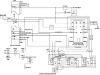
| Schematic Diagram: | 24-61-00 [ Global Express ] [ G5000 ] [ Global XRS ] |
| Wiring Diagram: | 24-61-01 [ Global Express ] [ G5000 ] [ Global XRS ] |
Fault Description:
Primary Logic Cards (PLC) detects a discrepancy between coil drive status and auxiliary contact status.
Possible Causes:
- DC Power Center (DCPC) Contactor K2
- DC Power Center (A63)
- Primary Logic Card (PLC) 1
- Primary Logic Card (PLC) 2
- Primary Logic Card (PLC) 3
- Electronic Module (EM) 3 (EM3)
- Associate Wiring
Troubleshooting Tips:
Advisory Wire/Service Bulletin: None
Forum Articles/Infoservice/Newsletter: None
Quick Links:
| Removal of the DC Power Center (DCPC) | AMM 24-61-00-000-801 [ Global Express ] [ G5000 ] [ Global XRS ] |
| Installation of the DC Power Center (DCPC) | AMM 24-61-00-400-801 [ Global Express ] [ G5000 ] [ Global XRS ] |
| Removal of the DC Power Center (DCPC) Primary Logic | AMM 24-61-09-000-801 [ Global Express ] [ G5000 ] [ Global XRS ] |
| Installation of the DC Power Center (DCPC) Primary Logic | AMM 24-61-09-400-801 [ Global Express ] [ G5000 ] [ Global XRS ] |
| Removal of the DC Power Center (DCPC)L-Series Contactor | AMM 24-61-53-000-801 [ Global Express ] [ G5000 ] [ Global XRS ] |
| Installation of the DC Power Center (DCPC)L-Series Contactor | AMM 24-61-53-400-801 [ Global Express ] [ G5000 ] [ Global XRS ] |
| Removal of the DC Power Center (DCPC) Electronic Modules | AMM 24-61-65-000-801 [ Global Express ] [ G5000 ] [ Global XRS ] |
| Installation of the DC Power Center (DCPC) Electronic Modules | AMM 24-61-65-400-801 [ Global Express ] [ G5000 ] [ Global XRS ] |
| Wire Repair - Maintenance Practices - ALL | SPM 20-12-10-02 [ Global Express ] [ G5000 ] [ Global XRS ] |
Troubleshooting Recommendations:
- On the DC synoptic page, make sure ESS TRU 1 icon is green and is supplying 28 VDC.
- Get access to the DCPC Contactor K2.
- Disconnect contactor K2 connector P304.
- In the cockpit, turn the BATT MSTR SW to ON.
- Perform a check for 28 VDC as follows:
From To Result P304-1 Ground P304-2 Ground - If there is 28 VDC, go to step 8.
- If there is no 28 VDC, continue with next step.
- Disconnect EM3 connector P305. Perform a check for 28 VDC as follows:
From To Result P305-23 Ground - If there is 28 VDC, continue with next step.
- If there is no voltage, go to step 15.
- Perform a continuity check as follows:
From To Result P305-25 P304-1 - If there is continuity, replace EM3 and do close out.
- If there is no continuity, go to step 15.
- Perform a continuity check as follows:
From To Result P304-5 Ground P304-7 Ground - If there is continuity, continue with next step.
- If there is no continuity, go to step 16.
- Remove PLC 1, PLC 2 and PLC 3.
- Perform a continuity check as follows:
From To Result P304-6 Ground P304-8 Ground P304-22 Ground P304-3 Ground - If there is continuity, go to step 15.
- If there is no continuity, continue with next step.
- Perform a continuity check as follows:
From To Result P304-3 P110C-20 P304-6 P110A-19 P304-8 P110A-20 P304-22 P110C-19 P304-3 P210C-20 P304-6 P210A-19 P304-8 P210A-20 P304-22 P210C-19 P304-3 P310C-20 P304-6 P310A-19 P304-8 P310A-20 P304-22 P310C-19 - If there is continuity, continue with next step.
- If there is no continuity, go to step 15.
- Install PLC 2 and PLC 3. Is the fault resolved.
- If YES, replace PLC 1 and do close out.
- If NO, install PLC 1 and remove PLC 2 and continue with next step.
- Replace PLC 2. Is the fault resolved?
- If YES, do close out.
- If NO, install PLC 2 and remove PLC 3 and continue with next step.
- Replace PLC 3. Is the fault resolved?
- If YES, do close out.
- If NO, reinstall PLC 3 and go to step 16.
- Replace contactor K2. Is the fault still present?
- If YES, continue with next step.
- If NO, do close out.
- Replace the DCPC.
- Do close out.