

06/27/19
Message Overview:
Fault Message:
FLAP SKEW SENSOR 3/ SFCU/ WRG
Fault Code:
2750034STD
Associated CAS:
| Reporting LRU: | Slat/Flap Control Unit (SFCU) |
| System Description: | 27-52-00 |
| Schematic Diagram: | 27-50-00 [ Global Express ] [ G5000 ] [ Global XRS ] |
| Wiring Diagram: | 27-50-03 [ Global Express ] [ G5000 ] [ Global XRS ] 27-50-04 [ Global Express ] [ G5000 ] [ Global XRS ] |
Fault Description:
One of the conditions that follow occur:
- Slat/Flap Control Unit (SFCU) does not receive input from Left Wing Flap Skew Sensor 3 (reported by SFCU 1)
- SFCU does not receive input from the Right Wing Flap Skew Sensor 3 (reported by SFCU 2)
- Input received by SFCU 1 or SFCU 2 is not in the permitted range
Possible Causes:
- Slat/Flap Control Unit (SFCU) 1 (A124)
- Slat/Flap Control Unit (SFCU) 2 (A95)
- Left Flap Skew Sensor 3
- Right Flap Skew Sensor 3
- Associated Wiring
Troubleshooting Tips:
Advisory Wire/Service Bulletin: None
Forum Articles/Infoservice/Newsletter: None
Skew values from SFCU 1 and SFCU 2 can be monitored by accessing CAIMS:
- SYSTEM DIAG
- 27-00 FLIGHT CONTROLS
- SLAT/FLAP CONTROL UNIT #1 (2)
- LRU TEST
- SLAT/FLAP POSITION - RAW DATA - SFCU1 (2)
- CONFIRM
- PAGE 2 OF 2
For Aircraft Pre SB 700-27-050 Skew 1 Skew 2 Skew 3 Skew 4 Recorded Value - - - - Calculated Value - - - - Recommended Value 9545 9496 8779 9518 Maximum Permissible 9575 9526 8809 9548 For Aircraft Post SB 700-27-050 Skew 1 Skew 2 Skew 3 Skew 4 Recorded Value - - - - Calculated Value - - - - Recommended Value 9545 9496 9387 9518 Maximum Permissible 9575 9526 9417 9548 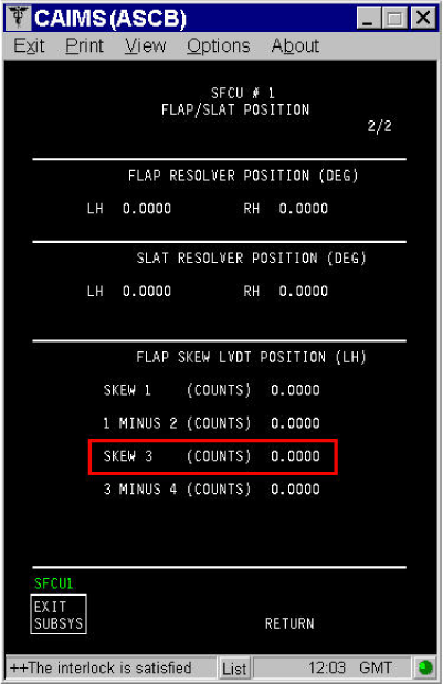
Quick Links:
| Removal of the Slat/Flap Control Unit (SFCU) | AMM 27-51-05-000-801 [ Global Express ] [ G5000 ] [ Global XRS ] |
| Installation of the Slat/Flap Control Unit (SFCU) | AMM 27-51-05-400-801 [ Global Express ] [ G5000 ] [ Global XRS ] |
| Removal of the Flap Skew Sensor | AMM 27-52-45-000-801 [ Global Express ] [ G5000 ] [ Global XRS ] |
| Installation of the Flap Skew Sensor | AMM 27-52-45-400-801 [ Global Express ] [ G5000 ] [ Global XRS ] |
| Access to System Diagnostics | AMM 45-45-00-970-804 [ Global Express ] [ G5000 ] [ Global XRS ] |
| Wire Repair - Maintenance Practices - ALL | SPM 20-12-10-02 [ Global Express ] [ G5000 ] [ Global XRS ] |
Troubleshooting Recommendations:
- Swap SFCUs.
- If system checks are good, replace defective SFCU and do close out.
- If fault remains, continue with next step.
- Perform resistance test of left skew sensor 3 and right skew sensor 3.
- If system checks are good, do close out.
- If fault remains, continue with next step.
NOTE: Resistance values for the skew detectors at ambient conditions (75 °F ±10 °F) or (24 °C ±4 °C).Left Flap Skew Sensor 3:
From To Resistance Range
P/N: GT415-5702-3 (5911043)/GT415-5702-5 (5913491)Result A124CP1-35 A124CP1-23 (Excitation) 120 ±20% ohms A124CP1-29 A124CP1-41 (Va) 93 ±15% ohms A124CP1-42 A124CP1-41 (Vb) 123 ±15% ohms Right Flap Skew Sensor 3:
From To Resistance Range
P/N: GT415-5702-3 (5911043)/GT415-5702-5 (5913491)Result A95CP1-35 A95CP1-23 (Excitation) 120 ±20% ohms A95CP1-29 A95CP1-41 (Va) 93 ±15% ohms A95CP1-42 A95CP1-41 (Vb) 123 ±15% ohms
- Perform wiring checks between left skew sensor 3 and SFCU 1; right skew sensor 3 and SFCU 2.
- If wiring checks are not good, repair defective wiring as required and do close out.
- If wiring checks are good, continue with next step.
- Replace Skew Sensor 3.
- Do close out.