

10/20/25
Message Overview:
Message Name:
HST MDU[CH2] NOT POWERED
Message Code:
27662232SX
Associated CAS:
| Reporting LRU: | Motor Drive Unit (MDU) |
| System Description: | 27-40-00 - Horizontal Stabilizer |
| Schematic Diagram: | [ Global Express ] [ G5000 ] [ Global XRS ] - 27-41-00 - Horizontal Stabilizer Pitch Trim System |
| Wiring Diagram: | [ Global Express ] [ G5000 ] [ Global XRS ] - 27-41-04 - Horizontal Stabilizer Pitch Trim System |
Message Description:
Horizontal Stabilizer Motor Drive Unit reported a loss of AC power going to Motor Drive Unit (MDU) Channel 2 or a failure of the internal power supply.
Possible Causes:
- Cockpit Circuit Breaker Panel (CCBP) (A35)
- Pitch Trim Actuator Motor Drive Unit (MDU) (A184)
- Associated Wiring
Troubleshooting Tips:
Advisory Wire/Service Bulletin: None
Full Throttle Blog/Forum Articles/Infoservice/Newsletter: None
Flight Operation Notifications Manual (FONM): None
NOTES:
- This CAIMS fault is posted when the following thermal breaker is pulled.
| LOCATION | CB NO. | NAME |
|---|---|---|
| CCBP-1 | E5 | STAB TRIM CH 2 |
- This fault may sometime be cleared by performing the flight control system reset procedure.
Quick Links:
| Standard Aircraft Configuration for Maintenance | [ G5000 ] [ Global Express ] [ Global XRS ] AMM12-00-00-867-801 |
| Aircraft Walkaround (for Maintenance) | [ G5000 ] [ Global Express ] [ Global XRS ] AMM12-00-00-867-802 |
| Connect Electrical Power to the Aircraft | [ G5000 ] [ Global Express ] [ Global XRS ] AMM24-00-00-861-801 |
| Remove the Electrical Power from the Aircraft | [ G5000 ] [ Global Express ] [ Global XRS ] AMM24-00-00-861-802 |
| Opening of Non-Thermal Circuit Breakers | [ G5000 ] [ Global Express ] [ Global XRS ] AMM24-00-00-863-801 |
| Closing of Non-Thermal Circuit Breakers | [ G5000 ] [ Global Express ] [ Global XRS ] AMM24-00-00-863-802 |
| Electrical/Electronic Safety Precautions | [ G5000 ] [ Global Express ] [ Global XRS ] AMM24-00-00-910-801 |
| Electrostatic Discharge Safety Precautions | [ G5000 ] [ Global Express ] [ Global XRS ] AMM24-00-00-910-802 |
| Operational Test (Cycling) of Thermal Circuit Breakers | [ G5000 ] [ Global Express ] [ Global XRS ] AMM24-00-00-710-802 |
| Operational Test of the Horizontal-Stabilizer Trim System | [ G5000 ] [ Global Express ] [ Global XRS ] AMM27-41-00-710-801 |
| Operational Test of the Pitch Trim Take-Off Configuration Warning | [ G5000 ] [ Global Express ] [ Global XRS ] AMM27-41-00-710-802 |
| Removal of the Pitch Trim Actuator-Motor | [ G5000 ] [ Global Express ] [ Global XRS ] AMM27-41-13-000-801 |
| Installation of the Pitch Trim Actuator-Motor | [ G5000 ] [ Global Express ] [ Global XRS ] AMM27-41-13-400-801 |
| Removal of the Pitch-Trim Actuator-Motor Drive-Unit | [ G5000 ] [ Global Express ] [ Global XRS ] AMM27-41-17-000-801 |
| Installation of the Pitch-Trim Actuator-Motor Drive-Unit | [ G5000 ] [ Global Express ] [ Global XRS ] AMM27-41-17-400-801 |
Troubleshooting Recommendations:
- Check status of STAB TRIM CH2 thermal (CCBP-E5).
- If circuit breaker tripped, go to step 3.
- If circuit breaker did not trip, continue with next step.
- Physically inspect the CCBP-E5 and then measure for 115 VAC at the MDU connector A184P5, pins A, B, C and pin D to aircraft ground.
From To Expected Result Result A184P5-A Ground 115 VAC A184P5-B Ground 115 VAC A184P5-C Ground 115 VAC A184P5-D GND 0 Ω - If checks are good continue with next step.
- If checks are not good repair as required and do close out.
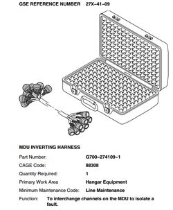
- Slave in a MDU and see if Active Fault clears.
- Use the Ground support Equipment 27X-41-09 "MDU INVERTING HARNESS" to isolate the fault to the MDU or Pitch Trim Actuator, prior to replacing any units.

- If the fault is isolated to the MDU, replace the MDU and do close out.
- If the fault is isolated to the HSTA, continue with the next step.
- Replace HSTA, do close out.
NOTE: The Pitch Trim Motors can be interchanged for confirmation before replacing a component. - Do close out.
- SYSTEM DIAG
- 27-00 FLIGHT CONTROLS
- FLIGHT CONTROL UNIT #2
- LRU TEST
- DISPLAY ADVANCED EFCS DATA
- Go to page 5 of 8
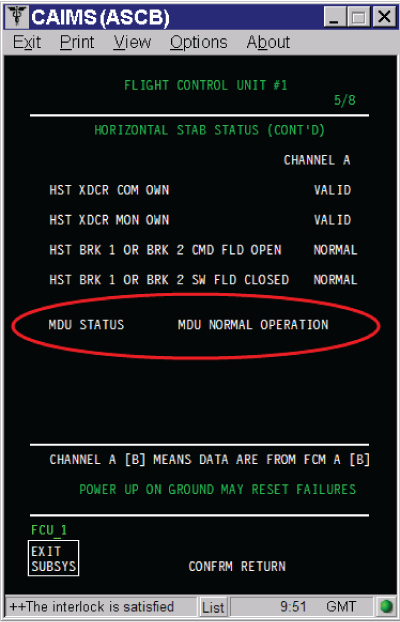

NOTE: The MDU status can be verified via CAIMS