

07/21/21
Message Overview:
Message Name:
HST MDU[CH2]/MOTOR #2/ACT/WRG FAULT
Message Code:
27662282SX
Associated CAS:
| Reporting LRU: | Motor Drive Unit (MDU) |
| System Description: | 27-40-00 |
| Schematic Diagram: | 27-41-00 [ Global Express ] [ G5000 ] [ Global XRS ] |
| Wiring Diagram: | 27-41-01 [ Global Express ] [ G5000 ] [ Global XRS ] |
Message Description:
CAIMS reports a Motor Drive Unit (MDU) Channel no response or a Actuator/Motor Jam.
Possible Causes:
- Pitch Trim Actuator Motor Drive Unit (A184)
- Pitch-Trim Actuator (B44)
- Flight Control Unit (FCU) 2 (A66)
- Pilot Master Disconnect Switch (S45)
- Copilot Master Disconnect Switch (A44)
- Associated Wiring
Troubleshooting Tips:
Advisory Wire/Service Bulletin: None
Forum Articles/Infoservice/Newsletter: None
NOTE: The present MDU-5 is known to be susceptible to nuisance coasting if there is a fast trim cycle of NOSE-UP or NOSE-DOWN. To prevent unnecessary troubleshooting and component removal after an occurrence of this phenomenon, it is recommended to do Flight Control Systems reset procedure before the next flight to determine if the STAB CH1 FAIL or STAB CH2 FAIL advisory or STAB TRIM caution message shows. If one of these messages still show after the self-test, it is necessary to do troubleshooting. If during subsequent flights a STAB CH1 FAIL or STAB CH2 FAIL message shows more than once in 10 flight legs, we suggest that operators record the CAIMS flight fault history for FCU 1 and FCU 2 if the faults reported are:
- H STAB MOT DR UNIT [CH1]/WRG FAULT
- H STAB MOT DR UNIT [CH2]/WRG FAULT
It can be necessary to replace the motor drive unit. Contact your local field service representative for further troubleshooting.
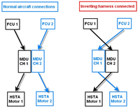
NOTE: You can use the MDU inverting Harness to help with troubleshooting.
Quick Links:
| Operational Test of the Stall Protection System - Dual Channel | AMM 27-32-00-710-802 [ Global Express ] [ G5000 ] [ Global XRS ] |
| Removal of the Pitch Trim Actuator | AMM 27-41-09-000-801 [ Global Express ] [ G5000 ] [ Global XRS ] |
| Installation of the Pitch Trim Actuator | AMM 27-41-09-400-801 [ Global Express ] [ G5000 ] [ Global XRS ] |
| Visual Check of the Pitch Trim Actuator | AMM 27-41-09-210-801 [ Global Express ] [ G5000 ] [ Global XRS ] |
| Removal of the Pitch-Trim Actuator-Motor Drive-Unit | AMM 27-41-17-000-801 [ Global Express ] [ G5000 ] [ Global XRS ] |
| Installation of the Pitch-Trim Actuator-Motor Drive-Unit | AMM 27-41-17-400-801 [ Global Express ] [ G5000 ] [ Global XRS ] |
| Removal of the Flight-Control Units | AMM 27-61-05-000-801 [ Global Express ] [ G5000 ] [ Global XRS ] |
| Installation of the Flight-Control Units | AMM 27-61-05-400-801 [ Global Express ] [ G5000 ] [ Global XRS ] |
| Wire Repair - Maintenance Practices - ALL | SPM 20-12-10-02 [ Global Express ] [ G5000 ] [ Global XRS ] |
Troubleshooting Recommendations:
- Perform the operational test of the Stall Protection System (AMM 27-32-00-710-802). Pay close attention to the portion of the test where the pilot and copilot MASTER DISC. switches are pressed.
- If the test passed, go to step 3.
- If the test did not pass while pushing on the pilot or copilot MASTER DISC switch, continue with next step.
- Perform a wiring checks between FCU 1 and FCU 2 to the Pilot and Copilot master disconnect switch.
NOTE: The master disconnect switch is not easy to access; the verification can be performed by doing a continuity check of the wire from the FCU through the switch and by selecting the switch.Pilot Master
Disconnect SwitchFrom To Normal Status Switch Selected A65AP1-8G A66AP1-8G open to ground Switch Not Selected A65AP1-8G A66AP1-8G shorted to ground Copilot Master
Disconnect SwitchFrom To Normal Status Switch Selected A65DP1-8D A66DP1-8D open to ground Switch Not Selected A65DP1-8D A66DP1-8D shorted to ground NOTE: Pilot Master Disconnect switch wire color code:
PIN (wire color) PIN (wire color) CONTACTS (Switch NOT Selected) CONTACTS (Switch Selected) A3 (blue) A2 (white) CLOSED OPEN B3 (violet) B2 (gray) CLOSED OPEN C3 (white/black) C2 (white/orange) CLOSED OPEN D4 (yellow) D1 (white/gray) OPEN CLOSED Make sure the pins on the terminal Module in the control wheel are locked properly. The terminal modules are not shown in the wiring diagram and system schematic.
- If wiring checks are not good, repair defective wiring as required and do close out.
- If wiring checks are good, continue with next step.
- Perform SPOST 1 and SPOST 2 of the FCUs at least twice. Is the fault still present?
- If YES, continue with next step.
- If NO, monitor and do close out.
- Interchange FCU 2 with FCU 1. Is the fault still present?
- If YES, continue with next step.
- If NO, replace FCU 2 and do close out.
- Use the Ground support Equipment 27X-41-09 "MDU INVERTING HARNESS" to isolate the fault to the MDU or pitch trim Actuator, prior to replacing any units.
- If the fault is suspected to be with the MDU, go to step 9.
- If the fault is suspected to be with the HSTA, continue with next step.
- Perform continuity checks between MDU and HSTA as follow:
From To Result A184P6-A B44P3-A A184P6-B B44P3-B A184P6-C B44P3-C From To Result A184P7-1 B44P4-34 A184P7-2 B44P4-26 A184P7-3 B44P4-12 A184P7-4 B44P4-11 A184P7-10 B44P4-32 A184P7-25 B44P4-33 A184P7-19 B44P4-14 A184P7-20 B44P4-13 - If there is continuity, continue with next step.
- If there is no continuity, repair defective wiring as required and do close out.
- Perform a continuity checks as follow:
From To Result A184P6-A Ground A184P6-B Ground A184P6-C Ground From To Result A184P7-1 Ground A184P7-2 Ground A184P7-3 Ground A184P7-4 Ground A184P7-10 Ground A184P7-25 Ground A184P7-19 Ground A184P7-20 Ground - If there is continuity, repair defective wiring as required and do close out.
- If there is no continuity, continue with next step.
- Swap the HSTA motors. Is the fault still present?
- If YES, continue with next step.
- If NO, replace defective HSTA motor and do close out.
- Replace the MDU.
- Do close out.
