11/30/20
Message Overview:
Fault Message:
RTL DISCNCT/RVDT#1 MISRIG FAULT
Fault Code:
27662331SX
Associated CAS:
| Reporting LRU: | Flight Control Unit (FCU) 1 |
| System Description: | 27-23-00 |
| Schematic Diagram: | 27-20-00 [ Global Express ] [ G5000 ] [ Global XRS ] |
| Wiring Diagram: | 27-20-02 [ Global Express ] [ G5000 ] [ Global XRS ] |
Fault Description:
There is erroneous readings from the RTL Position Transducer 1. This fault detected by the Flight Control Unit (FCU) 1 when the difference between the RTL XDCR 1 and 2 is more then 3 degrees.
Possible Causes:
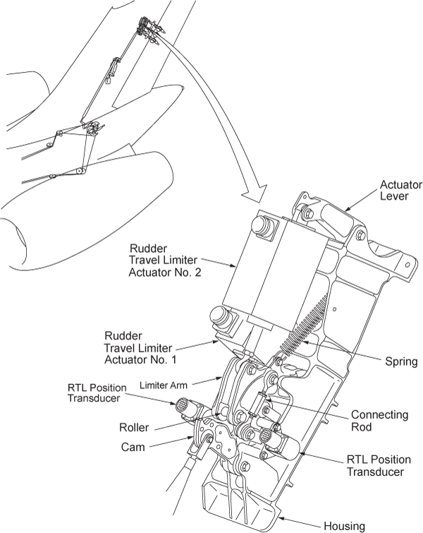
- Rudder Limiter Position Transducer 1 (MT130)
- Flight Control Unit (FCU) 1 (A65)
- Associated Wiring
Troubleshooting Tips:
Advisory Wire/Service Bulletin:
- Kavlico VSB 2011-0004 - Replacement of RVDTs on BD-700 aircraft
Forum Articles/Infoservice/Newsletter: None
NOTE: This fault may sometimes be cleared by performing the flight control system reset procedure. If the message comes back more then once within 10 flight legs, troubleshooting is required.
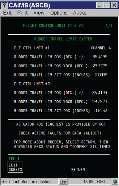
NOTE: The RTL values are displayed when FCU SPOST #1 or SPOST #2 (HYD ON) is successfully completed (i.e flight control reset procedure)
- RUDDER TRAVEL LIM POS XDCR (DEG) tolerance is ±0.5 DEG
- RUDDER TRAVEL LIM ACT POS (INCHES) tolerance is ±0.01 IN
The position of the RTL can be found in CAIMS:
- SYSTEM DIAG
- 27-00 FLIGHT CONTROLS
- FLIGHT CONTROL UNIT #1
- LRU TEST
- DISPLAY RUDDER TRAVEL LIM DATA
- CONFIRM
And
- SYSTEM DIAG
- 27-00 FLIGHT CONTROLS
- FLIGHT CONTROL UNIT #1
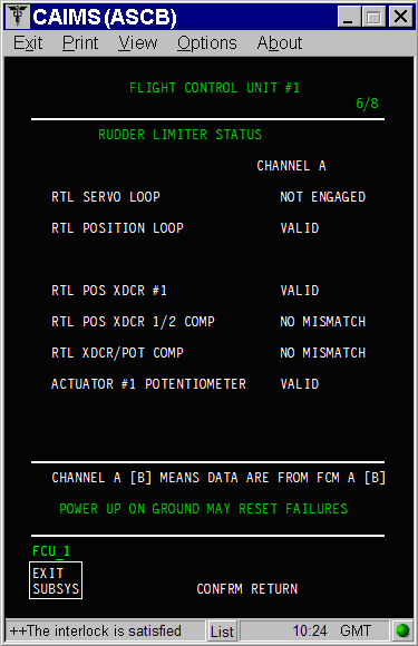
- LRU TEST
- DISPLAY ADVANCED EFCS DATA
- Go to page 6 of 8
If the cleared and can not be duplicated, the rudder limiter can be simulated on CAIMS:
- SYSTEM DIAG
- 27-00 FLIGHT CONTROLS
- FLIGHT CONTROL UNIT #1
- LRU TEST
- RUD TRAVEL LIM ACTR 1/2 POSITIONING
- CONFIRM
- Select the speed to be simulated then click on SELECT
Quick Links:
| Removal of the Rudder-Limiter Position Transducers | AMM 27-23-09-000-801 [ Global Express ] [ G5000 ] [ Global XRS ] |
| Installation of the Rudder Limiter Position Transducers | AMM 27-23-09-400-801 [ Global Express ] [ G5000 ] [ Global XRS ] |
| Adjustment of the Rudder-Limiter Position Transducers | AMM 27-23-09-820-801 [ Global Express ] [ G5000 ] [ Global XRS ] |
| Removal of the Flight-Control Units | AMM 27-61-05-000-801 [ Global Express ] [ G5000 ] [ Global XRS ] |
| Installation of the Flight-Control Units | AMM 27-61-05-400-801 [ Global Express ] [ G5000 ] [ Global XRS ] |
| Access to System Diagnostics | AMM 45-45-00-970-804 [ Global Express ] [ G5000 ] [ Global XRS ] |
| Wire Repair - Maintenance Practices - ALL | SPM 20-12-10-02 [ Global Express ] [ G5000 ] [ Global XRS ] |
Troubleshooting Recommendations:
- If one of the fault messages that follows reported together with this fault, perform troubleshooting of the other faults first.
Fault Message 27655241SX - RUD LIMITER POS XDCR #1/WRG FAULT 27661281SX - RUD LIMITER ACTR #1/ WRG FAULT 27662212SX - RUD LIMITER ACTR#1 POT/WRG FAULT - Access the DISPLAY RUDDER TRAVEL LIM DATA in CAIMS and record the value for the FCU 1 and FCU 2. If the RTL data is not updating steady perform wiring checks between FCU 1 and RTL position XDCR 1 (MT130).
- If wiring checks are not good, repair defective wiring as required and do close out.
- If wiring checks are good, continue with next step.
- If the value is reported properly but the difference between the position XDCR 1 and 2 is more then 3 degrees, perform the rigging of the position XDCR 1.
- If system checks are good, do close out.
- If fault remains, continue with next step.
NOTE: A new GSE was designed to adjust the XDCR.
NOTE: Make sure there are no loose hardware's in the RTL mechanism.
- Replace the RTL position XDCR 1, if it can't be adjusted.
- If system checks are good, do close out.
- If fault remains, continue with next step.
- Replace FCU 1 and reset FCUs latched faults.
- Do close out.