07/15/19
Message Overview:
Fault Message:
LH CTR XFER PUMP ELECT PWR/WRG
Fault Code:
284461EPK
Associated CAS:
| Reporting LRU: | Fuel Management and Quantity Gauging Computer (FMQGC) |
| System Description: | 28-22-00 |
| Schematic Diagram: | 28-22-00 [ Global Express ] [ G5000 ] [ Global XRS ] |
| Wiring Diagram: | 24-51-01 [ Global Express ] [ G5000 ] [ Global XRS ] 24-70-01 [ Global Express ] [ G5000 ] [ Global XRS ] 28-20-03 [ Global Express ] [ G5000 ] [ Global XRS ] 28-22-02 [ Global Express ] [ G5000 ] [ Global XRS ] 28-41-01 [ Global Express ] [ G5000 ] [ Global XRS ] |
Fault Description:
Left Center XFER Pump failed on or off due to:
- A failure of the Pump command signal from the Fuel Management Quantity and Gauging Computer (FMQGC) to the Electrical System, OR
- A failure of the Electrical System to power up or down the Pump when commanded by the FMQGC, OR
- A failure of the Electrical System to provide Pump power status feedback to the FMQGC
Possible Causes:
- Electrical Management System Control-and-Display Unit (EMS CDU) 1 (A94)
- Electrical Management System Control-and-Display Unit (EMS CDU) 2 (A91)
- AC Power Center (ACPC) (A54)
- Solid-State Power Controller (SSPC) 2 (A3)
- AC Power Center (ACPC) Microprocessor Card
- AC Power Center (ACPC) Supervisor Card
- Data Acquisition Unit (DAU) 1 (A17)
- Data Acquisition Unit (DAU) 2 (A18)
- Associated Wiring
Troubleshooting Tips:
Advisory Wire/Service Bulletin: None
Forum Articles/Infoservice/Newsletter: None
NOTE 1: Other names used for LEFT CENTER TRANSFER PUMP command signals:
- LH XFER L ENG RUN
- L XFER REQUEST
- L TRANSFER REQUEST
NOTE 2: You may use the EMS CDU to troubleshoot the CTR XFER PUMP message by using the following EMS CDU troubleshooting procedure.
Quick Links:
| Access of Signboard Menu in EMS CDU | AMM 24-00-00-946-801 [ Global Express ] [ G5000 ] [ Global XRS ] |
| Removal of the AC Power Center (ACPC) Fault-Tolerant Supervisor | AMM 24-51-01-000-801 [ Global Express ] [ G5000 ] [ Global XRS ] |
| Installation of the AC Power Center (ACPC) Fault-Tolerant Supervisor | AMM 24-51-01-400-801 [ Global Express ] [ G5000 ] [ Global XRS ] |
| Removal of the AC Power Center (ACPC) Fault-Tolerant Microprocessor | AMM 24-51-05-000-801 [ Global Express ] [ G5000 ] [ Global XRS ] |
| Installation of the AC Power Center (ACPC) Fault-Tolerant Microprocessor | AMM 24-51-05-400-801 [ Global Express ] [ G5000 ] [ Global XRS ] |
| Removal of the AC Power Center (ACPC) Solid-State Power Controller | AMM 24-51-53-000-801 [ Global Express ] [ G5000 ] [ Global XRS ] |
| Installation of the AC Power Center (ACPC) Solid-State Power Controller | AMM 24-51-53-400-801 [ Global Express ] [ G5000 ] [ Global XRS ] |
| Removal of the Electrical Management System Control-and-Display Units (EMS CDU) | AMM 24-70-01-000-801 [ Global Express ] [ G5000 ] [ Global XRS ] |
| Installation of the Electrical Management System Control-and-Display Units (EMS CDU) | AMM 24-70-01-400-801 [ Global Express ] [ G5000 ] [ Global XRS ] |
| Removal of the Data Acquisition Units (DAU) | AMM 31-42-01-000-801 [ Global Express ] [ G5000 ] [ Global XRS ] |
| Installation of the Data Acquisition Units (DAU) | AMM 31-42-01-400-801 [ Global Express ] [ G5000 ] [ Global XRS ] |
| Access to System Diagnostics | AMM 45-45-00-970-804 [ Global Express ] [ G5000 ] [ Global XRS ] |
| Wire Repair - Maintenance Practices - ALL | SPM 20-12-10-02 [ Global Express ] [ G5000 ] [ Global XRS ] |
Troubleshooting Recommendations:
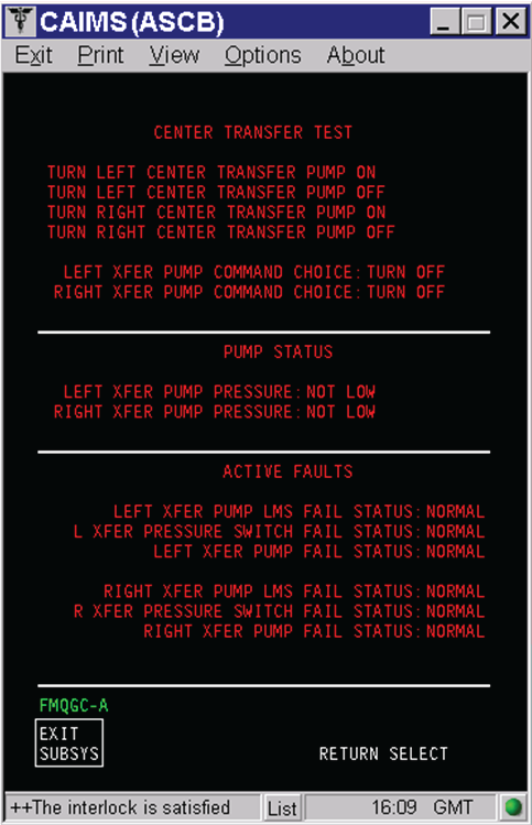
- Go to CENTER TRANSFER TEST page via PMAT to turn on Left Center Transfer Pump.
- Check L TRANSFER REQUEST command discrete input at EMS CDU as follows:
- In PMAT, select CH24-00 - Electrical Power.
- Select EMS CONT DISPLAY UNIT #1A.
- Select LTR TEST.
- Select DISCRETE INPUTS to display data.
- Ensure LEFT TRANSFER REQUEST command is ON.
- Repeat step 2 for EMS CONT DISPLAY 1B, 2A and 2B.
- If system checks are good, do close out.
- If fault remains, continue with next step.
- Check L CTR XFER PUMP command signals from the FMQGC to EMS CDU 1 and 2 (Two signal grounds at: A94P1-67 and A91P1-67).
- If checks are good, go to step 9.
- If fault remains, continue with next step.
- Perform wiring checks between FMQGC to Fuel Panel as follow:
From To Result A47AP1-K15 AP5P1-2 A47DP1-H13 AP5P1-3 - If wiring checks are not good, repair defective wiring as required and do close out.
- If wiring checks are good, continue with next step.
- Perform wiring checks between Fuel Panel to EMS CDU 1 and EMS CDU 2 as follow:
From To Result AP5P1-9 A94P1-67 AP5P1-4 A91P1-67 - If wiring checks are not good, repair defective wiring as required and do close out.
- If wiring checks are good, continue with next step.
- Perform wiring checks inside the Fuel Panel as follow:
From To Result AP5P1-2 AP5P1-9 AP5P1-3 AP5P1-4 - If wiring checks are not good, repair defective wiring as required and do close out.
- If wiring checks are good, continue with next step.
- Replace EMS CDU as required (CDU 1 for 1A and 1B command failure, CDU 2 for 2A and 2B command failure).
- If system checks are good, do close out.
- If fault remains, continue with next step.
- Check L CTR XFER PUMP load status from SSPC to EMS CDU as follows:
- In PMAT, select CH24-00 - Electrical Power.
- Select ACPC POWER CENTER ACPC A.
- Select LTR TEST.
- Select ACPC A, LOAD STATUS LABEL 002-007
- Select Label 003 load 2 - L CTR XFER PUMP Phase A.
- Ensure the following status are met.
Reference Status LOGIC EQUATION STATE (L TRANSFER REQUEST) ON VIRTUAL CIRCUIT BREAKER IN VIRTUAL SWITCH (SSPC SW) ON VOLTAGE STATUS PRESENT TRIP STATUS (CIRCUIT BREAKER) NOT TRIP FAIL STATUS (SSPC) NOT FAIL
- Repeat step 9 for phase B and phase C of the pump by selecting label 004 Load 1 (L CTR XFER PUMP Phase B) and label 004 Load 2 (L CTR XFER PUMP Phase C).
- If system checks are good, do close out.
- If fault remains, continue with next step.
- Check L CTR XFER PUMP feedback status from ACPC to EMS CDU 1 and CDU 2 as follows:
- Using EMS CDU 1 and CDU 2 Signboard Menu to select ACPC IN.
- Check L CTR XFER PUMP status, Label 276 Bit15 - Bit 18.
Left Column Center Column Label 276 L Ctr Xfer Status 29 28 27 26 25 24 23 22 21 20 19 18 17 16 15 14 X X X X X X X X X X X Bit 14-15 X = Ignore the values in the position shown by X 0000 = Pump OFF 0001 = Pump ON (V&I<20%) 0011 = Pump ON (V&I>20%) X1XX = SSPC TRIP 1XX0 = SSPC FAILED OFF 1XX1 = SSPC FAILED ON
- Does EMS CDU 1 agree with CDU 2 that L CTR XFER PUMP (ACPC IN) is Pump ON (V&I>20%)-(0011)?
- If system checks are good, do close out.
- If fault remains, continue with next step.
- Check L CTR XFER PUMP feedback status from EMS CDU 1 and CDU 2 to DAU 1 and DAU 2 as follows:
- Using EMS CDU 1 and CDU 2 Signboard Menu to select DAU OUT.
- Check L CTR XFER PUMP status, Label 276 Bit15 - Bit 18.
- Does EMS CDU 1 agree with CDU 2 that L CTR XFER PUMP (DAU OUT) is Pump ON (V&I>20%)-(0011)?
- If system checks are good, do close out.
- If fault remains, continue with next step.
- Replace defective DAU.
- Do close out.