10/07/25
Message Overview:
Message Name:
SHUTOFF VALVE OUTBD/BCU/WRG
Message Code:
3245316HA
| Reporting LRU: | Brake Control Unit (BCU) |
| Associated CAS: | NORM BRAKE FAIL (Warning) AUTOBRAKE FAIL (Caution) BRAKE 50% DEGRADED (Caution) BRAKE FAULT (Advisory) |
| System Description: | 32-43-00 - Brake Control System |
| Schematic Diagram: | [ G5000 ] [ Global Express ] [ Global XRS ] SSM 32-43-00-101 - Brake Control System - Electrical Schematic |
| Wiring Diagram: | [ G5000 ] [ Global Express ] [ Global XRS ] WM 32-43-00-3_002 - Sheet 2 - Right Hand Side - [9002] [ G5000 ] [ Global Express ] [ Global XRS ] WM 32-43-02-1_001 - Sheet 1 - Right - ALL |
Message Description:
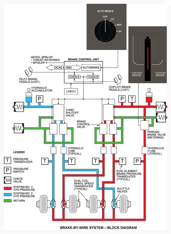
A discrepancy is detected between both Outboard Brakes and the Brake Control Unit (BCU) has switched the Outboard Brake Shut-off Valve (SOV) OFF.
Possible Causes:
- Left Outboard Brake Control Valve (BCV) (MT53)
- Right Outboard Brake Control Valve (BCV) (MT56)
- Outboard Brake Shut-Off Valve (SOV) (L14)
- Brake Control Unit (BCU) (A71)
- Associated Wiring
Troubleshooting Tips:
Advisory Wire/Service Bulletin:
- AW700-32-0244 - Operational Procedures to Prevent Freezing Brakes
- AW700-32-0359 - Brake Control System - Data Gathering to Reduce the Brake Control Unit (BCU) No-Fault-Found (NFF) rate
- AW700-32-0513 - Wheel Speed Transducer - Brake System Nuisance Fault Messages
- SB700-32-046 - Modification – Brake Control System – Introduction Of Restrictor On The Cylinder Port Of Brake Shut-off Valve (BSOV)
- SB700-1A11-32-033 - Modification – Brake Control System – Introduction Of Restrictor On The Cylinder Port Of Brake Shut-off Valve (BSOV)
Full Throttle Blog/Forum Articles/Infoservice/Newsletter: None
Flight Operation Notifications Manual (FONM): None
Quick Links:
| Standard Aircraft Configuration for Maintenance | [ G5000 ] [ Global Express ] [ Global XRS ] AMM12-00-00-867-801 |
| Connect Electrical Power to the Aircraft | [ G5000 ] [ Global Express ] [ Global XRS ] AMM24-00-00-861-801 |
| Electrical/Electronic Safety Precautions | [ G5000 ] [ Global Express ] [ Global XRS ] AMM24-00-00-910-801 |
| Electrostatic Discharge Safety Precautions | [ G5000 ] [ Global Express ] [ Global XRS ] AMM24-00-00-910-802 |
| Operational Test of the Brake System | [ G5000 ] [ Global Express ] [ Global XRS ] AMM32-43-00-710-801 |
| Pressure Test of the Brake System | [ G5000 ] [ Global Express ] [ Global XRS ] AMM32-43-00-780-801 |
| Removal of the Brake Control Unit | [ G5000 ] [ Global Express ] [ Global XRS ] AMM32-43-01-000-801 |
| Installation of the Brake Control Unit | [ G5000 ] [ Global Express ] [ Global XRS ] AMM32-43-01-400-801 |
| Removal of the Brake Control Valve | [ G5000 ] [ Global Express ] [ Global XRS ] AMM32-43-09-000-801 |
| Installation of the Brake Control Valve | [ G5000 ] [ Global Express ] [ Global XRS ] AMM32-43-09-400-801 |
| Removal of the Brake Shutoff Valve | [ G5000 ] [ Global Express ] [ Global XRS ] AMM32-43-25-000-801 |
| Installation of the Brake Shutoff Valve | [ G5000 ] [ Global Express ] [ Global XRS ] AMM32-43-25-400-801 |
| Operational Test of the Brake Shutoff Valve | [ G5000 ] [ Global Express ] [ Global XRS ] AMM32-43-25-710-801 |
| Access to Active Faults | [ G5000 ] [ Global Express ] [ Global XRS ] AMM45-45-00-970-802 |
| Access to Stored Faults | [ G5000 ] [ Global Express ] [ Global XRS ] AMM45-45-00-970-803 |
| Access to System Diagnostics | [ G5000 ] [ Global Express ] [ Global XRS ] AMM45-45-00-970-804 |
Troubleshooting Recommendations:
- Pressurize the hydraulic systems 2 and 3.
- Using CAIMS, access BRAKE CONTROL SYSTEM DATA PAGE 2 (System Data) as follow: System Diagnostic / ATA 32 - Landing Gear / Brake Control Unit / System Data Pages.
- Apply the brakes slowly, monitor the brake pressure (PSIG) at each brake position from the CAIMS System Data Pages.
- Release the brake pedals slowly and monitor the brake pressures. All four brake pressures must decrease at almost the same rate. Did the brake pressure decrease at the same rate and when the pedals are completely released the pressure value is below 95 PSIG at all four BCV?
- If YES, continue with the next step.
- If NO, inspect the associated BCV connector for proper installation, damage and contamination, repair as required, If nothing is identified continue with next step.
- Interchange BCVs for fault confirmation. Did the fault follow?
NOTE: Interchange the BCV with the opposite side. (i.e. Inboard BCV with Outboard BCV)- If YES, replace the defective BCV and do close out.
- If NO, continue with the next step.
- Disconnect BCU connector A71AP1 and Outboard Brake Shutoff Valve (SOV) connector L14P1. Do a continuity check as follows:
From To Expected Result Result L14P1-A Ground Open L14P1-B Ground Open - If there is no continuity, continue with next step.
- If there is continuity, replace the defective SOV and do close out.
- Perform a continuity check between outboard SOV (L14) and BCU (A71) as follows:
From To Expected Result Result L14P1-A A71AP1-8F Continuity L14P1-B A71AP1-8H Continuity - If there is no continuity, repair defective wiring as required and do close out.
- If there is continuity, continue with next step.
- Interchange the outboard and inboard Brake Shutoff Valves (SOV).
- If the fault follows the valve replace the defective valve.
- If the fault does not clear or if either channel of the BCU fails the Operational Check portion of Installation Task, after the interchange of the Brake SOVs replace BCU.
- Do close out.