10/09/24
Message Overview:
Message Name:
PRESSURE SWITCH INBD/WRG/BCU
Message Code:
3245319HA
| Reporting LRU: | Brake Control Unit (BCU) |
| Associated CAS: | INBD BRK LO PRESS (Caution) BRAKE FAULT (Advisory) |
| System Description: | 32-43-00 - Brake Control System |
| Schematic Diagram: | [ G5000 ] [ Global Express ] [ Global XRS ] SSM 32-43-00-101 - Brake Control System - Electrical Schematic |
| Wiring Diagram: | [ G5000 ] [ Global Express ] [ Global XRS ] WM 32-43-00-1_004 - Sheet 4 - Indication - [9004-9024] [ G5000 ] [ Global Express ] [ Global XRS ] WM 32-43-00-2_004 - Sheet 4 - Indication - [9003, 9025-9158] [ G5000 ] [ Global Express ] [ Global XRS ] WM 32-43-00-3_004 - Sheet 4 - Indication - [9002] |
Message Description:
The Brake Control Unit (BCU) detected a disagreement condition between the System 3 (Inboard) Brake Pressure Switch Channel A and Channel B.
Possible Causes:
- System 3 (SYS) Brake Pressure Switch (S5)
- Brake Control Unit (BCU) (A71)
- Associated Wiring
Troubleshooting Tips:
Advisory Wire/Service Bulletin:
- AW700-32-0138 - Loss of Normal Braking Upon Landing
- AW700-32-0244 - Operational Procedures to Prevent Freezing Brakes
- AW700-32-0359 - Brake Control System - Data Gathering to Reduce the Brake Control Unit (BCU) No-Fault-Found (NFF) rate
- AW700-32-0513 - Wheel Speed Transducer - Brake System Nuisance Fault Messages
- SB700-32-016 - MODIFICATION - BRAKE CONTROL SYSTEM - PART NO. CHANGE OF THE BRAKE CONTROL UNIT TO GW415-7125-5
Full Throttle Blog/Forum Articles/Infoservice/Newsletter: None
Flight Operation Notifications Manual (FONM): None
NOTES:
- If you replace a brake system component please fill out this questionnaire.
Quick Links:
| Grounding of the Aircraft | [ G5000 ] [ Global Express ] [ Global XRS ] AMM10-11-00-867-801 |
| Removal of the Covers and Plugs | [ G5000 ] [ Global Express ] [ Global XRS ] AMM10-12-00-020-801 |
| Installation of the Covers and Plugs | [ G5000 ] [ Global Express ] [ Global XRS ] AMM10-12-00-420-801 |
| Standard Aircraft Configuration for Maintenance | [ G5000 ] [ Global Express ] [ Global XRS ] AMM12-00-00-867-801 |
| Aircraft Walkaround (for Maintenance) | [ G5000 ] [ Global Express ] [ Global XRS ] AMM12-00-00-867-802 |
| Connect Electrical Power to the Aircraft | [ G5000 ] [ Global Express ] [ Global XRS ] AMM24-00-00-861-801 |
| Remove the Electrical Power from the Aircraft | [ G5000 ] [ Global Express ] [ Global XRS ] AMM24-00-00-861-802 |
| Electrical/Electronic Safety Precautions | [ G5000 ] [ Global Express ] [ Global XRS ] AMM24-00-00-910-801 |
| Electrostatic Discharge Safety Precautions | [ G5000 ] [ Global Express ] [ Global XRS ] AMM24-00-00-910-802 |
| Operational Test of the Brake System | [ G5000 ] [ Global Express ] [ Global XRS ] AMM32-43-00-710-801 |
| Operational Test of the No. 3 Hydraulic-System Brake Pressure-Switch | [ G5000 ] [ Global Express ] [ Global XRS ] AMM32-43-00-710-802 |
| Removal of the Brake Control Unit | [ G5000 ] [ Global Express ] [ Global XRS ] AMM32-43-01-000-801 |
| Installation of the Brake Control Unit | [ G5000 ] [ Global Express ] [ Global XRS ] AMM32-43-01-400-801 |
| Removal of the No. 2 Hydraulic-System Brake Pressure-Switch | [ G5000 ] [ Global Express ] [ Global XRS ] AMM32-43-49-000-801 |
| Installation of the No. 2 Hydraulic-System Brake Pressure-Switch | [ G5000 ] [ Global Express ] [ Global XRS ] AMM32-43-49-400-801 |
| Removal of the No. 3 Hydraulic-System Brake Pressure-Switch | [ G5000 ] [ Global Express ] [ Global XRS ] AMM32-43-51-000-801 |
| Installation of the No. 3 Hydraulic-System Brake Pressure-Switch | [ G5000 ] [ Global Express ] [ Global XRS ] AMM32-43-51-400-801 |
| Access to Active Faults | [ G5000 ] [ Global Express ] [ Global XRS ] AMM45-45-00-970-802 |
| Access to Stored Faults | [ G5000 ] [ Global Express ] [ Global XRS ] AMM45-45-00-970-803 |
| Access to System Diagnostics | [ G5000 ] [ Global Express ] [ Global XRS ] AMM45-45-00-970-804 |
| Flight Deck Effect to Fault Correlations | [ G5000 ] [ Global Express ] [ Global XRS ] AMM45-45-00-970-821 |
| Wire Repair - Maintenance Practices - ALL | [ G5000 ] [ Global Express ] [ Global XRS ] SPM20-12-10-02 |
Troubleshooting Recommendations:
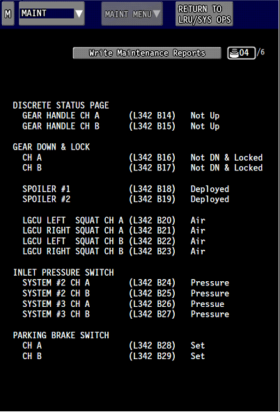
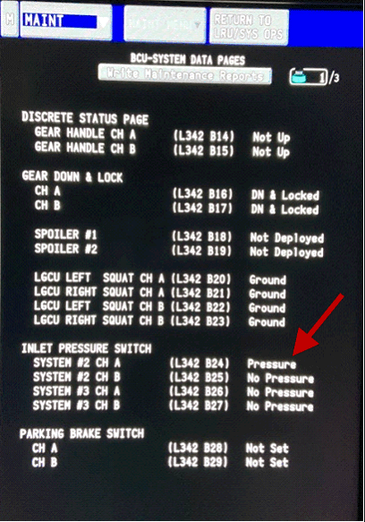
- Using CAIMS, access ATA 32, BCU, BRAKE CONTROL SYSTEM DATA PAGE 21 (DISCRETE INPUT STATUS).
- With the hydraulic system 3 OFF, the INLET PRESSURE SWITCH for SYSTEM 3 CH A and CH B should show NO PRESSURE.
- Pressurize hydraulic system 3 and the INLET PRESSURE SWITCH for SYSTEM 3 CH A and CH B should show PRESSURE.
- Re-seat the BCU, making sure it is fully and properly inserted into place.
- If fault indication is gone, do close out.
- If fault remains, continue with next step.
- Remove the BCU, make sure hydraulic system 2 is not pressurized. Perform a continuity check as follows:
From To Result A71AP1-10H A71AP1-9G A71BP1-5E A71BP1-4D - If there is continuity, go to step 5.
- If there is no continuity, continue with next step.
- Apply pressure to hydraulic system 3.
- Perform a continuity check as follows:
From To Result A71AP1-10H A71AP1-9G A71BP1-5E A71BP1-4D - If there is continuity, go to step 7.
- If there is no continuity, continue with next step.
- Perform a continuity check between the Inboard brake pressure switch S5 and BCU as follows:
From To Expected Result Result S5P1-1 A71AP1-10H Continuity A71BP1-5E A71BP1-4D Continuity S5P1-2 A71AP1-9G Continuity S5P1-4 A71BP1-5E Continuity S5P1-5 A71BP1-4D Continuity A71AP1-10H Ground Open A71AP1-9G Ground Open A71BP1-5E Ground Open A71BP1-4D Ground Open - If wiring defects are found, repair defective wiring as required and do close out.
- If the wiring checks are good, continue with next step.
- Replace the system 3 brake pressure switch (S5). Is the fault still present?
- If YES, continue with next step.
- If NO, do close out.
- Replace the BCU.
- Do close out.