09/10/19
Message Overview:
Fault Message:
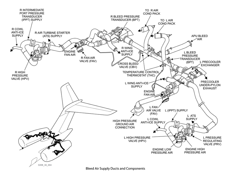
LEFT BLEED AIR DUCTS RUPTURE
Fault Code:
3615417BMC
Associated CAS:
| Reporting LRU: | Bleed Management Controller (BMC) 1 |
| System Description: | 36-11-00 |
| Schematic Diagram: | 36-11-00 [ Global Express ] [ G5000 ] [ Global XRS ] |
| Wiring Diagram: | 36-11-01 [ Global Express ] [ G5000 ] [ Global XRS ] |
Fault Description:
The Bleed Management Controller (BMC) 1 senses that the opposite bleed pressure is higher by 10 pound per square inch (gage) (PSIG) when the Cross-Bleed Valve is fully open and the Left Bleed-Pressure Regulating and Shut-off Valve is closed.
Possible Causes:
- Bleed Pressure Transducer (BPT) 1 (MT96)
- Junction Box 3 (JB3)/PCB2
- Bleed Management Controller (BMC) 1 (A69)
- Associated Wiring
Troubleshooting Tips:
Advisory Wire/Service Bulletin:
- AW700-36-0365 - Bleed Management Controller - Data Gathering to reduce No Fault Found (NFF) rate
Forum Articles/Infoservice/Newsletter:
- Forum Article 2011-VOL 8 issue 23 - Bleed Management Controller (BMC) Top 10 No Fault Found (NFF) vs. Reliability Improvement Modification Program (RIMP) implementation
Questionnaire for replacing the BMC. Follow instructions using this (Fill out form)
NOTE: Always verify you are working with the current document revision. Access the CIC website to ensure the latest document revision.
Test Points on Junction Box for troubleshooting reference - 31-42-00 DAU1 GP Bus TP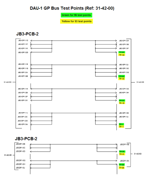
Quick Links:
| Removal of the Junction Box JB3 | AMM 24-00-01-000-801 [ Global Express ] [ G5000 ] [ Global XRS ] |
| Installation of the Junction Box JB3 | AMM 24-00-01-400-801 [ Global Express ] [ G5000 ] [ Global XRS ] |
| Removal of the Junction Box JB3 Circuit-Cards | AMM 24-00-02-000-801 [ Global Express ] [ G5000 ] [ Global XRS ] |
| Installation of the Junction Box JB3 Circuit-Cards | AMM 24-00-02-400-801 [ Global Express ] [ G5000 ] [ Global XRS ] |
| Leak Test of the Bleed Air System | AMM 36-11-00-790-801 [ Global Express ] [ G5000 ] [ Global XRS ] |
| Removal of the Bleed Pressure Transducer | AMM 36-11-25-000-801 [ Global Express ] [ G5000 ] [ Global XRS ] |
| Installation of the Bleed Pressure Transducer | AMM 36-11-25-400-801 [ Global Express ] [ G5000 ] [ Global XRS ] |
| Removal of the Bleed Management Controller | AMM 36-11-33-000-801 [ Global Express ] [ G5000 ] [ Global XRS ] |
| Installation of the Bleed Management Controller | AMM 36-11-33-400-801 [ Global Express ] [ G5000 ] [ Global XRS ] |
| Removal of the Bleed Air Ducts | AMM 36-11-45-000-801 [ Global Express ] [ G5000 ] [ Global XRS ] |
| Installation of the Bleed Air Ducts | AMM 36-11-45-400-801 [ Global Express ] [ G5000 ] [ Global XRS ] |
| Wire Repair - Maintenance Practices - ALL | SPM 20-12-10-02 [ Global Express ] [ G5000 ] [ Global XRS ] |
Troubleshooting Recommendations:
- Inspect LEFT bleed ducts for duct integrity and signs of rupture.
- If faults are found, adjust the couplings, remove and reinstall or replace the faulty components as required and do close out.
- If faults are not found, continue with next step.
- Perform the leak test of bleed air system.
- If fault transfers, do close out.
- If fault persists, continue with next step.
- Swap Bleed pressure transducer (BPT) 1 with Bleed pressure transducer (BPT) 2 and inspect BPT sense line.
- If fault transfers, replace BPT 1 and do close out.
- If fault persists, reinstall BPTs in their original positions and continue with next step.
- Swap Bleed Management Computer (BMC) 1 with Bleed Management Computer (BMC) 2.
- If fault transfers, replace BMC 1 and do close out.
- If fault persists, reinstall BMCs in their original positions then continue with next step.
- Perform wiring checks Between BPT, JB3 PCB2 and BMC 1.
- If wiring checks are not good, repair defective wiring as required and do close out.
- If wiring checks are good, continue with next step.
- Perform continuity check of JB3/PCB2.
- If there is no continuity, repair defective wiring as required and do close out.
- If there is continuity, continue with next step.
- Replace JB3/PCB2.
- Do close out.