

09/13/19
Message Overview:
Fault Message:
APU SHT DN-INL DOOR FAILURE TO OPEN
Fault Code:
4960121APU
Associated CAS:
| Reporting LRU: | Full-Authority Digital Engine-Controller (FADEC) |
| System Description: | 49-60-00 |
| Schematic Diagram: | 49-14-00 [ Global Express ] [ G5000 ] [ Global XRS ] |
| Wiring Diagram: | 49-12-01 [ Global Express ] [ G5000 ] [ Global XRS ] 49-61-01 [ Global Express ] [ G5000 ] [ Global XRS ] |
Fault Description:
The Full-Authority Digital Engine-Controller (FADEC) did not let the Auxiliary Power Unit (APU) start because the Inlet Door was not in the correct position prior to the start.
| Fault | See * below | Description |
|---|---|---|
| FADEC FAILURE | ECU internal failure (CPU, watchdog timer, O/S circuit failure, loss of O/S protection, etc.) |
|
| O/SPD | (Hardware/Software) overspeed circuits tripped (at 106%) | |
| LOSS OF SPEED | Both monopoles failed | |
| LOSS OF O/SPD | FADEC overspeed circuit/FCU fuel output solenoid failed | |
| OVERTEMP | * | EGT limit exceeded during i) start ii) on-speed operation |
| FIRE EMERG | * | Fire signal is received by the FADEC |
| REVERSE FLOW | * | T2 temp. limit (176.6 °C/350 °F) has been exceeded for 5 secs |
| HIGH OIL TEMP | * | Oil temp limit of >148.9 °C exceeded for 10 seconds |
| LOW OIL PRESS | * | Oil pressure has fallen below lower limit of 30 psig for 15 seconds, with rpm >95% |
| LOSS OF EGT DETECTION | * | Both EGT thermocouples have failed ( NOTE: In Essential Mode, FADEC programs an EGT of 260 °C to maintain the APU running) |
| NO FLAME | EGT rise has not been detected within 17 seconds of fuel solenoid being commanded open by FADEC, or rpm >18% for 5 seconds |
|
| NO ACCEL | Acceleration is < 0.05% of the prescheduled rate (normal acceleration is 2.5% per seconds). | |
| SLOW SPEED | Starter timer expired - APU rpm > 5% and less than starter cut out for 30 seconds | |
| UNDER SPEED | * | Speed has reached 100%, then drops below 80% for 5 secs |
| NO CRANK | rpm does not rise above 5% within: a) 2 secs. when oil temp is warmer than minus 23 °C, or b) 50 secs. when oil temp is minus 23 °C or lower |
|
| INLET DOOR | Inlet door position indicates closed 30 secs before starter engagement, or 600 msecs. after starter engagement |
|
| LOSS OF DC POWER | Loss of 28 VDC power for 200 milliseconds. | |
| LOP SW FAIL | * | Oil pressure switch has failed open when rpm is <7% ( NOTE: This switch is normally closed during prestart BITE) |
| FALLBACK | APU drop below 25% rpm after starter cutout | |
| APU GCU HIGH OIL TEMP | * | APU Generator oil temperature above 215 °C |
NOTE: An asterisk mark (*) in any row above means that the automatic protection shut down on that row is inhibited if the associated fault occurs in flight. The respective CAS message, or an advisory message reading APU FAULT will be displayed in the CAS window and the APU will not shut down automatically in flight. However the pilot may select to shut down the APU manually by placing the APU Control Switch to OFF.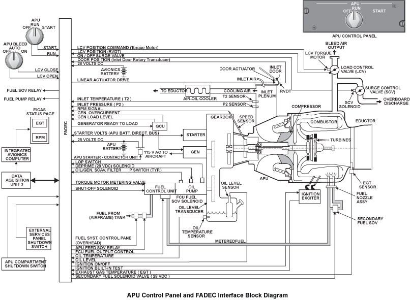
Possible Causes:
- Linear Actuator (A199)
- Auxiliary Power Unit (APU) Full-Authority Digital Engine-Controller (FADEC) (A108)
- Associated Wiring
Troubleshooting Tips:
Advisory Wire/Service Bulletin: None
Forum Articles/Infoservice/Newsletter: None
The FADEC provides BITE information as to the door position or status and logic to prevent starting in the event the door fails closed when in the "closed" position.
The condition would occur when the inlet door failed to open within 30 seconds of the FADEC energizing the door actuator.
The inlet door position will be indicated on the status page only if the door position does not agree with FADEC's command. On such occasions, the number of degrees of door opening will appear as an amber digital readout against a white placard marked APU DOOR, between the spaces designated for OIL QTY and BRAKE TEMP.
Quick Links:
| Removal of the Linear Actuator | AMM 49-14-05-000-801 [ Global Express ] [ G5000 ] [ Global XRS ] |
| Installation of the Linear Actuator | AMM 49-14-05-400-801 [ Global Express ] [ G5000 ] [ Global XRS ] |
| Removal of the Full-Authority Digital Engine-Controller (FADEC) | AMM 49-61-01-000-801 [ Global Express ] [ G5000 ] [ Global XRS ] |
| Installation of the Full-Authority Digital Engine-Controller (FADEC) | AMM 49-61-01-400-801 [ Global Express ] [ G5000 ] [ Global XRS ] |
| Wire Repair - Maintenance Practices - ALL | SPM 20-12-10-02 [ Global Express ] [ G5000 ] [ Global XRS ] |
Troubleshooting Recommendations:
- Disconnect the A199P1 connector from the linear actuator (A199). Examine linear actuator receptacle (A199) for contamination and damage.
- Perform a continuity check between actuator connector and ground as follows:
From To Expected Result Result A199P1-A Ground > 1 megaohm A199P1-B Ground > 1 megaohm - If resistance checks are not good, repair defective wiring as required and do close out.
- If resistance checks are good, continue with next step.
- Disconnect the P803 connector at the APU firewall interface (FS1046 LHS).
- Perform a continuity check between connector P803 and Linear actuator as follows:
From To Expected Result Result A199P1-A P803-L < 1 ohm A199P1-B P803-M < 1 ohm A199P1-C P803-E < 1 ohm A199P1-D P803-F < 1 ohm - If resistance checks are not good, repair defective wiring as required and do close out.
- If resistance checks are good, continue with next step.
- Perform a continuity check between the connectors of linear actuator as follows:
From To Expected Result Result A199P1-A A199P1-B > 1 megaohm A199P1-C A199P1-D > 1 megaohm - If resistance checks are not good, repair defective wiring as required and do close out.
- If resistance checks are good, continue with next step.
- Disconnect the J803 connector at the APU firewall interface (FS1046 LHS) and disconnect the A48P1 connector from the APU start contactor assembly (A48).
- Perform a continuity check between P803 connectors as follows:
From To Expected Result Result P803-L P803-E < 3 ohms - If resistance checks are not good, repair defective wiring as required and do close out.
- If resistance checks are good, continue with next step.
- Remove the FADEC (A108) and perform a continuity check between P803 connectors and FADEC as follows:
From To Expected Result Result P803-E A108BP1-C4 < 3 ohms P803-F A108BP1-D4 < 3 ohms - If resistance checks are not good, repair defective wiring as required and do close out.
- If resistance checks are good, continue with next step.
- Perform a continuity check on connector J803 as follows:
From To Expected Result Result J803-E J803-F > 1 megaohm - If resistance checks are not good, repair defective wiring as required and do close out.
- If resistance checks are good, continue with next step.
- Replace APU FADEC.
- Do close out.