

09/13/19
Message Overview:
Fault Message:
NO DATA- EGT SENSOR [CKT 1 & 2]/WRG
Fault Code:
4960126APU
Associated CAS:
| Reporting LRU: | Full Authority Digital Engine (Electronic) Control (FADEC) |
| System Description: | 49-40-00 |
| Schematic Diagram: | 49-61-00 [ Global Express ] [ G5000 ] [ Global XRS ] |
| Wiring Diagram: | 49-61-01 [ Global Express ] [ G5000 ] [ Global XRS ] |
Fault Description:
Failure or loss of signal from Exhaust Gas Temperature (EGT) Sensor 1 and EGT Sensor 2. On ground, Auxiliary Power Unit (APU) will auto shutdown or will not start. In flight the APU continues to operate and CAS displays APU EGT SENSORS caution message.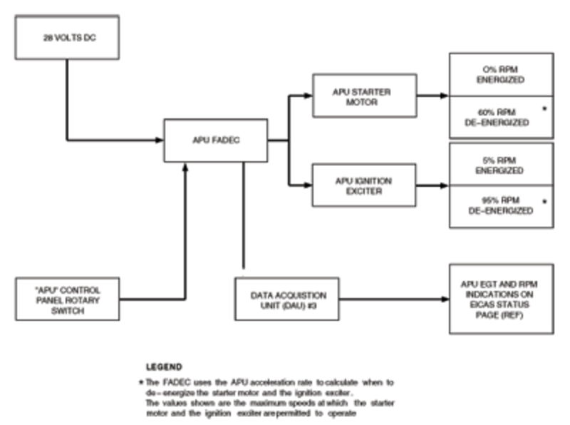
Possible Causes:
- Exhaust Gas Temperature (EGT) Sensor (TC1)
- Auxiliary Power Unit (APU) Full-Authority Digital Engine-Controller (FADEC) (A108)
- Associated Wiring
Troubleshooting Tips:
Advisory Wire/Service Bulletin:
- AW700-49-0538 - Auxiliary Power Unit (APU) Exhaust Gas Temperature (EGT) Sensor
Forum Articles/Infoservice/Newsletter:
- Honeywell SIL-APU-87 - AIRBORNE AUXILIARY POWER - GAS TURBINE ENGINE - RE220GX APU Auto Shutdown in Heavy Rain
If CAS message is not active, verify stored faults on CAIMS, under System Diagnostics, ATA 49 (this will include ground and air faults).
Quick Links:
| Access to Active Faults | AMM 45-45-00-970-802 [ Global Express ] [ G5000 ] [ Global XRS ] |
| Access to Stored Faults | AMM 45-45-00-970-803 [ Global Express ] [ G5000 ] [ Global XRS ] |
| Access to System Diagnostics | AMM 45-45-00-970-804 [ Global Express ] [ G5000 ] [ Global XRS ] |
| Removal of the Engine Branched Wiring-Harness | AMM 49-12-01-000-801 [ Global Express ] [ G5000 ] [ Global XRS ] |
| Installation of the Engine Branched Wiring-Harness | AMM 49-12-01-400-801 [ Global Express ] [ G5000 ] [ Global XRS ] |
| Removal of the Full-Authority Digital Engine-Controller (FADEC) | AMM 49-61-01-000-801 [ Global Express ] [ G5000 ] [ Global XRS ] |
| Installation of the Full-Authority Digital Engine-Controller (FADEC) | AMM 49-61-01-400-801 [ Global Express ] [ G5000 ] [ Global XRS ] |
| Removal of the Exhaust Gas Temperature (EGT) Sensor | AMM 49-61-05-000-801 [ Global Express ] [ G5000 ] [ Global XRS ] |
| Installation of the Exhaust Gas Temperature (EGT) Sensor | AMM 49-61-05-400-801 [ Global Express ] [ G5000 ] [ Global XRS ] |
| Wire Repair - Maintenance Practices - ALL | SPM 20-12-10-02 [ Global Express ] [ G5000 ] [ Global XRS ] |
Troubleshooting Recommendations:
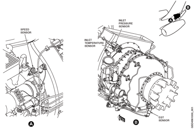
- Visually Inspect the EGT Sensors for signs of water that would cause a short between the posts. Use Honeywell SIL-APU-87 if needed.
- If system checks are good, do close out.
- If fault remains, continue with next step.
- Access CAIMS and using active faults, or stored faults find the fault and verify the CAS message. You can use System Diagnostics to view each channel of the APU FADEC (each EGT sensor) in real time and also access ground faults.
- Inspect the wiring and connectors to the EGT sensors for any damage.
- If damage found, repair as required and do close out.
- If damage not found, continue with next step.
- Inspect the EGT sensors for condition and check that the resistance between the Alumel and Chromel post of each sensor is less than 20 ohms.
- If resistance not within range, repair as required and do close out.
- If resistance within range, continue with next step.
- Inspect for RTV sealant per Honeywell SIL-APU-87 (latest Rev).
- Replace a defective EGT probe as per Honeywell SIL-APU-87 from the vendor.
- If system checks are good, do close out.
- If fault remains continue with next step.
- Re-rack FADEC and verify connector A108BP1 pins B-K6, B-K5, B-K8 and B-K7 for damage or FOD, verify if fault is still present.
- If system checks are good, do close out.
- If fault remains continue with next step.
- Replace APU FADEC.
- Do close out.