04/14/22
Message Overview:
Message Name:
MULTIPLE ACPC CONTACTORS K4 K6 K9 AND K12 POSTED SIMULTANEOUSLY IN CAIMS
(i.e. K4, K6, K9, and K12)
| Identifier: | 243OBS003 |
| Effectivity: | All |
| System: | Electrical Power |
| Associated CAS: | ELEC SYS FAULT (Advisory) |
| System Description: | 24-60-00 |
| Schematic Diagram: | 24-62-01 [ Global Express ] [ G5000 ] [ Global XRS ] |
| Wiring Diagram: | 24-62-01 [ Global Express ] [ G5000 ] [ Global XRS ] 24-62-05 [ Global Express ] [ G5000 ] [ Global XRS ] |
Message Description:
The AC Power Center (ACPC) Primary Logic Cards (PLCs) detect a discrepancy during the contactor's power-on Built-In Test (BIT), which causes multiple Generator Transfer Contactors (GTCs) to be reported failed.
Possible Causes:
- Alternate DC Power Distribution (ADCPD) 5 (AP77)
- Secondary Power Distribution Assembly (SPDA) 2 (A14)
- Generator Control Unit (GCU) 1 (A56)
- Generator Control Unit (GCU) 2 (A57)
- Generator Control Unit (GCU) 3 (A58)
- Generator Control Unit (GCU) 4 (A59)
- APU Generator Control Unit (GCU) (A109)
- Associated Wiring
Troubleshooting Tips:
Advisory Wire/Service Bulletin:
- AW700-24-0252 - "ELEC SYS FAULT" and or "ELEC SYS FAIL" - Nuisance CAS Message during Power-Up
Forum Articles/Infoservice/Newsletter:
Flight Operation Notifications Manual (FONM): None
NOTE: If the condition described above is experienced on your aircraft, consider disconnecting the aircraft batteries every day as the APU battery may drain very quickly.
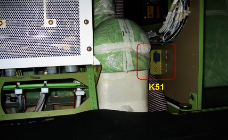
Quick fault Confirmation of K51 failure:
Before applying Battery power (BMS) and external AC power on the aircraft, pull ACPC CTL PWR D CB located on the ASCA. Put BMS to ON and apply external AC power on the aircraft.
If the ELEC SYS FAULT and/or ELEC SYS FAIL CAS and the contactor CAIMS messages are no longer posted, suspect K51 and continue troubleshooting below.
Quick Links:
| Removal of the Generator Control Units (GCU) | AMM 24-24-01-000-801 [ Global Express ] [ G5000 ] [ Global XRS ] |
| Installation of the Generator Control Units (GCU) | AMM 24-24-01-400-801 [ Global Express ] [ G5000 ] [ Global XRS ] |
| Removal of the Secondary-Power Distribution Assemblies | AMM 24-62-01-000-801 [ Global Express ] [ G5000 ] [ Global XRS ] |
| Installation of the Secondary-Power Distribution Assemblies | AMM 24-62-01-400-801 [ Global Express ] [ G5000 ] [ Global XRS ] |
| Removal of the Aft Alternate DC-Power-Distribution (ADCPD) Relay | AMM 24-65-05-000-801 [ Global Express ] [ G5000 ] [ Global XRS ] |
| Installation of the Aft Alternate DC-Power-Distribution (ADCPD) Relay | AMM 24-65-05-400-801 [ Global Express ] [ G5000 ] [ Global XRS ] |
| Operational Test of the Aft Alternate DC-Power-Distribution (ADCPD) Relay | AMM 24-65-05-710-801 [ Global Express ] [ G5000 ] [ Global XRS ] |
| Wire Repair - Maintenance Practices - ALL | SPM 20-12-10-02 [ Global Express ] [ G5000 ] [ Global XRS ] |
Troubleshooting Recommendations:
- Get access to the K51 relay. (Baggage area, below GCUs)
- Perform a electrical check while the power is OFF on the aircraft (Batt Master Switch to OFF), as follows:
From To Expected Result Result K51P1-A1 Ground 28 VDC - If there is no voltage, go to step 4.
- If there is voltage, continue with next step.
NOTE: The K51 relay may be intermittent, therefore, a few power cycles may be required to confirm the fault on the A/C
- Perform a continuity check while K51 is removed from the A/C to confirm K51 replacement as follows:
From To Result K51-A1 K51-A2 - If there is no continuity, repair defective wiring as required and do close out.
- If there is continuity, continue with next step.
- Disconnect all 5 GCUs and apply power to the A/C.
- If the fault is still present, go to step 6.
- If the fault is no longer present, continue with next step.
- Reconnect one GCU at a time, monitoring the fault at every power-up until the fault resumes.
- If the fault does not resume, do close out.
- If the fault resumes, replace GCU and do close out.
- Replace SPDA 2 and monitor for further occurrences of the ELEC SYS FAULT CAS message.
- Do close out.