12/23/19
Message Overview:
Fault Message:
DCPC SSPC#4-K10 POWER UP FAILED
Fault Code:
2463006DCP
Associated CAS:
| Reporting LRU: | DC Power Center (DCPC) |
| System Description: | 24-60-00 |
| Schematic Diagram: | 24-61-00 [ Global Express ] [ G5000 ] [ Global XRS ] |
| Wiring Diagram: | 24-61-01 [ Global Express ] [ G5000 ] [ Global XRS ] |
Fault Description:
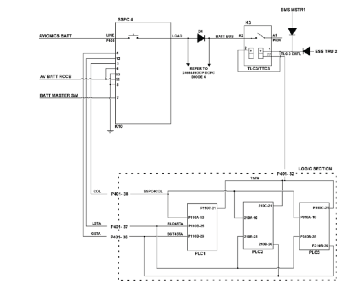
When voltage is present on Avionics BATT DIRECT BUS while DC Power Center (DCPC) Solid State Power Controller (SSPC) 4 is off and there is voltage on the SSPC 4 output, the Power-up Built-In Test (PBIT) will fail. This will indicate SSPC 4 or D4 short circuit fault.
Possible Causes:
- Solid State Power Controller 4 (SSPC)
- DC Power Center (DCPC) Diode (D4)
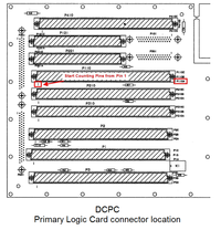
- Primary Logic Card (PLC) 1
- Primary Logic Card (PLC) 2
- Primary Logic Card (PLC) 3
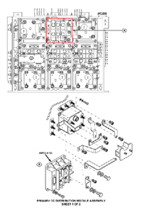
- DC Power Center (DCPC) (A63)
- Associated Wiring
Troubleshooting Tips:
Advisory Wire/Service Bulletin: None
Forum Articles/Infoservice/Newsletter: None
Quick Links:
| Removal of the DC Power Center (DCPC) | AMM 24-61-00-000-801 [ Global Express ] [ G5000 ] [ Global XRS ] |
| Installation of the DC Power Center (DCPC) | AMM 24-61-00-400-801 [ Global Express ] [ G5000 ] [ Global XRS ] |
| Removal of the DC Power Center (DCPC) Primary Logic | AMM 24-61-09-000-801 [ Global Express ] [ G5000 ] [ Global XRS ] |
| Installation of the DC Power Center (DCPC) Primary Logic | AMM 24-61-09-400-801 [ Global Express ] [ G5000 ] [ Global XRS ] |
| Removal of the DC Power Center (DCPC) P700-Series Contactors | AMM 24-61-21-000-801 [ Global Express ] [ G5000 ] [ Global XRS ] |
| Installation of the DC Power Center (DCPC) P700-Series Contactors | AMM 24-61-21-400-801 [ Global Express ] [ G5000 ] [ Global XRS ] |
| DC Power Center (DCPC) Assembly | CMM 24-61-02 [ Global Express ] [ G5000 ] [ Global XRS ] |
| Wire Repair - Maintenance Practices - ALL | SPM 20-12-10-02 [ Global Express ] [ G5000 ] [ Global XRS ] |
Troubleshooting Recommendations:
- Get access to CAIMS active faults. Is message 2460449DCP DCPC DIODE 4 (D4) FAILED displayed?
- If YES, troubleshoot this message first.
- If NO, continue with next step.
- Disconnect SSPC4 (K10) connector P403. Remove all three Primary Logic Cards (PLC 1, PLC 2 and PLC 3) from the DCPC. Perform a continuity check of SSPC 4 Coil status, load status and gate status as follows:
From To Result P403-3 Ground P403-4 Ground P403-12 Ground - If there is continuity, go to step 8.
- If there is no continuity, continue with next step.
- Perform a continuity check at the PLC connectors in the DCPC as follows:
From To Result P403-3 P110A-10 P403-3 P210A-10 P403-3 P310A-10 P403-4 P110B-26 P403-4 P210B-26 P403-4 P310B-26 P403-12 P110B-25 P403-12 P210B-25 P403-12 P310B-25 - If there is no continuity, go to step 8.
- If there is continuity, continue with next step.
- While SSPC4 (K10) connector P403 is still disconnected, set the Battery Master Switch to ON. Perform a 28 VDC voltage check as follows:
From To Result P403-7 Ground - If 28 VDC is present, go to step 6.
- If 28 VDC is not present at pin 7, continue with next step.
- Perform wiring checks from SSPC 4 (K10) to the Battery Master switch.
- If no wiring defects are found, check continuity/function of the battery master switch directly on the electrical control panel. Replace if required.
- If wiring defects are found, repair defective wiring as required and do close out.
- Replace SSPC 4 (K10). Is the fault resolved?
- If YES, do close out
- If NO, continue with next step.
- Perform SmartFix Plus task for fault code 2460449DCP.
- If system checks are good, do close out.
- If fault remains, continue with next step.
- Replace DCPC.
- Do close out.