

07/10/19
Message Overview:
Fault Message:
AIR DATA CMPTR #2/ BUS #2 FAULT
Fault Code:
27660292SX
Associated CAS:
| Reporting LRU: | Flight Control Unit (FCU) 2 |
| System Description: | 27-60-00 |
| Schematic Diagram: | 27-60-00 [ Global Express ] [ G5000 ] [ Global XRS ] |
| Wiring Diagram: | 27-60-02 [ Global Express ] [ G5000 ] [ Global XRS ] 34-11-03 [ Global Express ] [ G5000 ] [ Global XRS ] |
Fault Description:
Flight Control Unit (FCU) 2 does not receive data from Micro Air Data Computer (MADC) 2.
Possible Causes:
- Micro Air Data Computer (MADC) 2 (A28)
- Junction Box (JB6)
- Flight Control Unit (FCU) 2 (A66)
- Associated Wiring
Troubleshooting Tips:
Advisory Wire/Service Bulletin:
- AW700-45-0065 - CAIMS Nuisance Fault Messages
Forum Articles/Infoservice/Newsletter: None
NOTE: No action required, if it is reported in the fault history only.
This fault may sometime be cleared by performing the flight control system reset procedure.
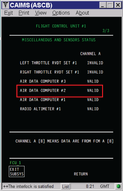
The status of the MADC#2 can be found in CAIMS:
- SYSTEM DIAG
- 27-00 FLIGHT CONTROLS
- FLIGHT CONTROL UNIT #2
- LRU TEST
- DISPLAY MISC. & SENSORS STATUS
- Go to page 3 of 3
Quick Links:
| Removal of the Junction Box JB6 | AMM 24-00-13-000-801 [ Global Express ] [ G5000 ] [ Global XRS ] |
| Installation of the Junction Box JB6 | AMM 24-00-13-400-801 [ Global Express ] [ G5000 ] [ Global XRS ] |
| Removal of the Junction Box JB6 Circuit-Cards | AMM 24-00-14-000-801 [ Global Express ] [ G5000 ] [ Global XRS ] |
| Installation of the Junction Box JB6 Circuit-Cards | AMM 24-00-14-400-801 [ Global Express ] [ G5000 ] [ Global XRS ] |
| Removal of the Flight-Control Units | AMM 27-61-05-000-801 [ Global Express ] [ G5000 ] [ Global XRS ] |
| Installation of the Flight-Control Units | AMM 27-61-05-400-801 [ Global Express ] [ G5000 ] [ Global XRS ] |
| Removal of the Micro Air-Data Computers | AMM 34-11-09-000-801 [ Global Express ] [ G5000 ] [ Global XRS ] |
| Installation of the Micro Air-Data Computers | AMM 34-11-09-400-801 [ Global Express ] [ G5000 ] [ Global XRS ] |
| Access to Active Faults | AMM 45-45-00-970-802 [ Global Express ] [ G5000 ] [ Global XRS ] |
| Access to System Diagnostics | AMM 45-45-00-970-804 [ Global Express ] [ G5000 ] [ Global XRS ] |
| Electronic Junction Box | CMM 24-00-01 [ Global Express ] [ G5000 ] [ Global XRS ] |
| Wire Repair - Maintenance Practices - ALL | SPM 20-12-10-02 [ Global Express ] [ G5000 ] [ Global XRS ] |
Troubleshooting Recommendations:
- If the CAS message ADC 2 FAIL is posted, troubleshoot it first.
- Measure for 4.4 VDC or higher at JB6 test points for ARINC 429 Bus.
- If voltage is not present, go to step 7.
- If voltage is present, continue with next step.
ARINC 429 Bus For 93 pins Test point Connector
(JB6 PCB4 P/N 00514-0129-0002)JB6 (JB6FP1) FCU 2 (A66DP1) MADC 2 (A28P1) High TP - 63 JB6FP1-6H, JB6FP1-6K, JB6FP1-7B and JB6FP1-7D A66DP1-8K A28P1-63 Low TP - 64 JB6FP1-6J, JB6FP1-7A, JB6FP1-7C and JB6FP1-7E A66DP1-8J A28P1-64 ARINC 429 Bus For 96 pins Test point Connector
(JB6 PCB4 P/N 00514-0129-0001)JB6 (JB6FP1) FCU 2 (A66DP1) MADC 2 (A28P1) High TP - 65 JB6FP1-6H, JB6FP1-6K, JB6FP1-7B and JB6FP1-7D A66DP1-8K A28P1-63 Low TP - 66 JB6FP1-6J, JB6FP1-7A, JB6FP1-7C and JB6FP1-7E A66DP1-8J A28P1-64 NOTE: The test point’s references inside the junction boxes in the wiring diagram are not accurate. (Reference CMM24-00-01)
NOTE: Pin to pin and pin to ground wiring check can be done through the JB test point. DO NOT perform an insulation test through the junction box.
- Measure for 4.4 VDC at FCU 2 for ARINC 429 Bus.
- If voltage is present, go to step 9.
- If voltage is not present, continue with next step.
- Perform wiring checks between FCU 2 and JB6 test points.
- If wiring checks are not good, repair defective wiring as required and do close out.
- If wiring checks are good, continue with next step.
- Replace JB6 Circuit Board 4 (JB6 PCB4).
- If system checks are good, do close out.
- If fault remains, continue with next step.
- Replace JB6 and do close out.
- If system checks are good, do close out.
- If fault remains, continue with next step.
- Measure for 4.4 VDC or higher at Engine Firewall connector 2JA2 pins 34 and 35 for ARINC 429 Bus.
- If voltage is present, go to step 5.
- If voltage is not present, continue with next step.
- Measure for short circuit for shorted to ground, shorted to shield, and shorted between wires of ARINC 429 Bus.
- If system checks are good, do close out.
- If fault remains, continue with next step.
NOTE: Remove MADC 2, FCU 2 and Engine Firewall connector (2PA2 and 2PB4) for this test.
- Swap FCU 2 with FCU 1.
- If system checks are good, replace FCU 1. Reset FCUs latched faults and do close out.
- If fault remains, continue with next step.
- Swap MADCs.
- If system checks are good, replace MADC 2 and do close out.
- If fault remains, continue with next step.
- Perform wiring checks between MADC 2 and JB6 test points for ARINC 429 Bus.
- If wiring checks are not good, repair defective wiring as required and do close out.
- If wiring checks are good, continue with next step.
- Replace MADC 2.
- Do close out.