10/20/25
Message Overview:
Message Name:
HST MDU[CH1] NOT POWERED
Message Code:
27662231SX
Associated CAS:
| Reporting LRU: | Motor Drive Unit (MDU) |
| System Description: | 27-40-00 - Horizontal Stabilizer |
| Schematic Diagram: | [ Global Express ] [ G5000 ] [ Global XRS ] 27-41-00 Horizontal Stabilizer Pitch Trim System |
| Wiring Diagram: | [ Global Express ] [ G5000 ] [ Global XRS ] 27-41-04 Motor Drive Unit |
Message Description:
Horizontal Stabilizer Motor Drive Unit reported a loss of AC power going to Motor Drive Unit (MDU) Channel 1 or a failure of the internal power supply.
Possible Causes:
- AC Power Center (ACPC) (A54)
- Pitch Trim Actuator Motor Drive Unit (MDU) (A184)
- Associated Wiring
Troubleshooting Tips:
Advisory Wire/Service Bulletin: None
Full Throttle Blog/Forum Articles/Infoservice/Newsletter: None
Flight Operation Notifications Manual (FONM): None
NOTES:
- This fault is posted when the following thermal breaker is pulled.
Location CB No. Name ACPC B6 STAB TRIM CH 1 - This fault may sometime be cleared by performing the flight control system reset procedure. If the message comes back more then once within 10 flight legs, perform the following troubleshooting.
- Verify C/B status on both pilot and copilot EMS CDUs. This CAS Message will post if either of the following circuit breaker or Smart Contactor status is OUT or Tripped.
LOCATION CB No. NAME ACPC (A54) CB-B6 STAB TRIM CH1 ACPC (A54) SC-K15 AC 1 FEED
Quick Links:
| Standard Aircraft Configuration for Maintenance | [ G5000 ] [ Global Express ] [ Global XRS ] AMM12-00-00-867-801 |
| Aircraft Walkaround (for Maintenance) | [ G5000 ] [ Global Express ] [ Global XRS ] AMM12-00-00-867-802 |
| Connect Electrical Power to the Aircraft | [ G5000 ] [ Global Express ] [ Global XRS ] AMM24-00-00-861-801 |
| Remove the Electrical Power from the Aircraft | [ G5000 ] [ Global Express ] [ Global XRS ] AMM24-00-00-861-802 |
| Opening of Non-Thermal Circuit Breakers | [ G5000 ] [ Global Express ] [ Global XRS ] AMM24-00-00-863-801 |
| Closing of Non-Thermal Circuit Breakers | [ G5000 ] [ Global Express ] [ Global XRS ] AMM24-00-00-863-802 |
| Electrical/Electronic Safety Precautions | [ G5000 ] [ Global Express ] [ Global XRS ] AMM24-00-00-910-801 |
| Electrostatic Discharge Safety Precautions | [ G5000 ] [ Global Express ] [ Global XRS ] AMM24-00-00-910-802 |
| Operational Test (Cycling) of Thermal Circuit Breakers | [ G5000 ] [ Global Express ] [ Global XRS ] AMM24-00-00-710-802 |
| Operational Test of the Horizontal-Stabilizer Trim System | [ G5000 ] [ Global Express ] [ Global XRS ] AMM27-41-00-710-801 |
| Operational Test of the Pitch Trim Take-Off Configuration Warning | [ G5000 ] [ Global Express ] [ Global XRS ] AMM27-41-00-710-802 |
| Removal of the Pitch Trim Actuator-Motor | [ G5000 ] [ Global Express ] [ Global XRS ] AMM27-41-13-000-801 |
| Installation of the Pitch Trim Actuator-Motor | [ G5000 ] [ Global Express ] [ Global XRS ] AMM27-41-13-400-801 |
| Removal of the Pitch-Trim Actuator-Motor Drive-Unit | [ G5000 ] [ Global Express ] [ Global XRS ] AMM27-41-17-000-801 |
| Installation of the Pitch-Trim Actuator-Motor Drive-Unit | [ G5000 ] [ Global Express ] [ Global XRS ] AMM27-41-17-400-801 |
Troubleshooting Recommendations:
- Check status of AC 1 FEED on EMS CDU, the AC 1 Feed being out or tripped can drive multiple CAS to post.
BUS > AC 1 > AC 1 FEED.- If AC 1 FEED CB is IN go to step 3.
- If AC 1 FEED CB is OUT, set to IN.
AC 1 FEED CB SYSTEM PHASE CAS CB-G6 ESS TRU 1 3 AC BUS 1 FAIL (Caution) CB-G3 EVS FAIRING HEAT 3 EVS HEAT FAIL (Caution) CB-G9 SLAT/FLAP PWR 1 3 SLAT-FLAP HALFSPD (Advisory) CB-H5 EVS WINDOW HEAT 1 EVS HEAT FAIL (Caution) CB-H6 A/T CTLR 1 A/T 1 FAIL (Advisory)
A/T 2 FAIL (Advisory)CB-H7 PITOT 1 HT A 1 PITOT 1 HT FAIL (Caution) CB-H8 R ICE DETECTOR 1 ICE DETECTOR FAULT (Advisory) CB-H9 R AOA HEAT A 1 R AOA HEAT FAIL (Caution) CB-H10 L WSHLD HEAT 1 1 L WSHLD HEAT FAIL (Caution) CB-H11 L WSHLD HEAT 2 1 R WSHLD HEAT FAIL (Caution) CB-H12 TRU BAY FAN 3 ELEC SYS FAULT (Advisory) CB-B6 STAB TRIM CH1 3 STAB CH 1 FAIL (Advisory)
- Did the CAIMS Fault & CAS messages clear after setting AC 1 FEED CB to IN.
- If YES, do close out.
- If NO, go to next step.
- Check status of STAB TRIM CH 1 Non-Thermal Circuit Breaker (CB-B6).
- If circuit breaker is tripped, go to step 5.
- If circuit breaker did not trip, continue with next step.
- Perform voltage checks between MDU connector A184P1 to aircraft ground as follow:
From To Expected Result Result A184P1-A Ground 115 VAC A184P1-B Ground 115 VAC A184P1-C Ground 115 VAC - If checks are good, go to step 6.
- If any of check fails, continue with next step.
- Disconnect the connector A184P1 and reset the CB. If the CB trip again. Perform wiring checks between MDU and ACPC.
- If wiring checks are not good, repair defective wiring as required and do close out.
- If wiring checks are good, continue with next step.
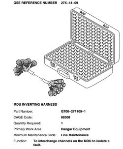
- Use the Ground support Equipment 27X-41-09 "MDU INVERTING HARNESS" to confirm the fault, prior to replacing any units.

- If the fault is isolated to the MDU, replace the MDU and do close out.
- If the fault is isolated to the HSTA, continue with the next step
- Replace HSTA, do close out.
NOTE: The Pitch Trim Motors can be interchanged for confirmation before replacing a component. - Do close out.

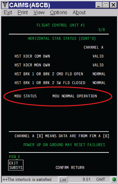
NOTE: The MDU status can be verified via CAIMS.
- SYSTEM DIAG.
- 27-00 FLIGHT CONTROLS.
- FLIGHT CONTROL UNIT #1.
- LRU TEST.
- DISPLAY ADVANCED EFCS DATA.
- Go to page 5 of 8.