04/25/25
Message Overview:
Message Name:
[BMC1] TRIM AIR LEAK D LOOP /WRG
Message Code:
3615525BMC
| Reporting LRU: | Bleed Management Controller 1 (BMC) |
| Associated CAS: | TRIM AIR FAIL (Caution) TRIM AIR FAULT (Advisory) |
| System Description: | 36-12-00 - Bleed-Air Leak-Detection System |
| Schematic Diagram: | [ G5000 ] [ Global Express ] [ Global XRS ] SSM 36-12-00-101 - Bleed Air Leak Detection System - Electrical Schematic |
| Wiring Diagram: | [ G5000 ] [ Global Express ] [ Global XRS ] WM 36-12-00-1_003 - Sheet 3 - Center/AFT Fuselage - [9004-9024] [ G5000 ] [ Global Express ] [ Global XRS ] WM 36-12-03-1_001 - Sheet 1 - Centre/Aft Fuselage - ALL |
Message Description:
The Trim Air Loop circuit connected to Bleed Management Controller 1 (BMC) has been detected with an Open Center Conductor or short circuit between the Center Conductor and the Outer Sheath. Inhibited during Take-Off and Landing.
Possible Causes:
- Bleed Air Leak-Detection System
- Trim Air Loops
- Bleed Management Controller 1 (BMC) (A69)
- Associated Wiring
Troubleshooting Tips:
Advisory Wire/Service Bulletin:
- AW700-36-0365 - Bleed Management Controller - Data Gathering to Reduce No Fault Found (NFF) Rate
- AW700-36-0826 - Kidde Bleed Leak Detection Loops Notice of Escape
Full Throttle Blog/Forum Articles/Infoservice/Newsletter:
- Forum Article 2011-VOL 8 issue 23 - Bleed Management Controller (BMC) Top 10 No Fault Found (NFF) vs. Reliability Improvement Modification Program (RIMP) implementation
- Questionnaire for replacing the BMC. Follow instructions using this (Fill out form)
Flight Operation Notifications Manual (FONM): None
NOTES:
- Always verify you are working with the current document revision. Access the CIC website to ensure the latest document revision.
- Refer to AIPC 36-12-03 for Left outboard Wing A/ICE Leak Detection Loops.
- The sensing element is used to find a temperature that is too hot. When the eutectic salt is heated to its alarm temperature, it forms a conductive path between the center wire conductor and the outer sheath of the sensing element. This path transmits a signal that gives an alarm signal to the detection circuit.
- Let the temperature of the sensing element become stable at ambient room temperature. Write the temperature.
- To prevent damage to the sensing element connector, install test pins in the connectors when you do the continuity and insulation resistance tests.
CAUTION:
- WHEN PERFORMING THE CONDUCTANCE TEST OF THE LEAK DETECTION LOOPS, DO NOT USE A METER THAT APPLIES DC VOLTAGE. DO NOT USE INSULATION RESISTANCE “MEGGER” TESTERS OR DIELECTRIC VOLTAGE “HYPOT” TESTERS. THESE WILL DAMAGE THE SENSING ELEMENT.
- DO NOT DO TESTS OF A SENSING ELEMENT THAT IS HEATED TO WITHIN 100°F (55°C) OF ITS ALARM TEMPERATURE.
Quick Links:
| Grounding of the Aircraft | [ G5000 ] [ Global Express ] [ Global XRS ] AMM10-11-00-867-801 |
| Removal of the Covers and Plugs | [ G5000 ] [ Global Express ] [ Global XRS ] AMM10-12-00-020-801 |
| Installation of the Covers and Plugs | [ G5000 ] [ Global Express ] [ Global XRS ] AMM10-12-00-420-801 |
| Standard Aircraft Configuration for Maintenance | [ G5000 ] [ Global Express ] [ Global XRS ] AMM12-00-00-867-801 |
| Aircraft Walkaround (for Maintenance) | [ G5000 ] [ Global Express ] [ Global XRS ] AMM12-00-00-867-802 |
| Connect Electrical Power to the Aircraft | [ G5000 ] [ Global Express ] [ Global XRS ] AMM24-00-00-861-801 |
| Remove the Electrical Power from the Aircraft | [ G5000 ] [ Global Express ] [ Global XRS ] AMM24-00-00-861-802 |
| Electrical/Electronic Safety Precautions | [ G5000 ] [ Global Express ] [ Global XRS ] AMM24-00-00-910-801 |
| Electrostatic Discharge Safety Precautions | [ G5000 ] [ Global Express ] [ Global XRS ] AMM24-00-00-910-802 |
| Removal of the Bleed Management Controller | [ G5000 ] [ Global Express ] [ Global XRS ] AMM36-11-33-000-801 |
| Installation of the Bleed Management Controller | [ G5000 ] [ Global Express ] [ Global XRS ] AMM36-11-33-400-801 |
| Operational Test of the Bleed Management Controller | [ G5000 ] [ Global Express ] [ Global XRS ] AMM36-11-33-710-801 |
| Bleed Leak-Detection-Loops and Components Maintenance Practices | [ G5000 ] [ Global Express ] [ Global XRS ] AMM36-12-00-910-801 |
| Operational Test of the Bleed Leak-Detection-Loops | [ G5000 ] [ Global Express ] [ Global XRS ] AMM36-12-01-710-801 |
| Access to Active Faults | [ G5000 ] [ Global Express ] [ Global XRS ] AMM45-45-00-970-802 |
| Access to Stored Faults | [ G5000 ] [ Global Express ] [ Global XRS ] AMM45-45-00-970-803 |
| Access to System Diagnostics | [ G5000 ] [ Global Express ] [ Global XRS ] AMM45-45-00-970-804 |
| Flight Deck Effect to Fault Correlations | [ G5000 ] [ Global Express ] [ Global XRS ] AMM45-45-00-970-821 |
| Wire Repair - Maintenance Practices - ALL | [ G5000 ] [ Global Express ] [ Global XRS ] SPM20-12-10-02 |
Troubleshooting Recommendations:
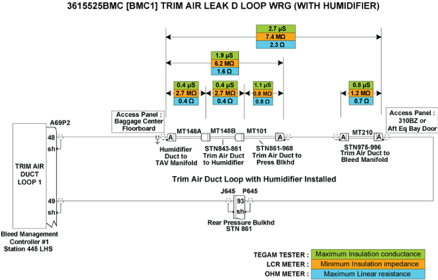
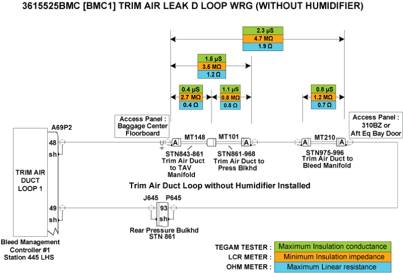
- Disconnect A69P2 from BMC 1.
- Measure Insulation resistance and line resistance of the detection loops as per the Leak Detection Elements troubleshooting sheet. Make sure line resistance & insulation values are within the specified limits.
- If the values are within specified limits, go to step 4.
- If values are not within the specified limits, continue with next step.
- Replace faulty elements.
- If system checks are good, do close out.
- If fault remains, continue with next step.
- Make sure the Leak Detection Elements are installed as per Bleed Air Leak Detection System-Maintenance Practices.
- If system checks are good, do close out.
- If fault remains, continue with next step.
- Perform wiring checks of the remaining wires linking the Trim Air Loops circuit to BMC 1.
- If wiring checks are not good, repair defective wiring as required and do close out.
- If wiring checks are good, continue with next step.
- Replace BMC 1.
- Do close out.