04/24/25
Message Overview:
Message Name:
[BMC2] RIGHT BLEED LEAK D LOOP /WRG
Message Code:
3616523BMC
| Reporting LRU: | Bleed Management Controller 2 (BMC) |
| Associated CAS: | R BLEED SYS FAIL (Caution) R BLEED FAULT (Advisory) |
| System Description: | 36-12-00 - Bleed-Air Leak-Detection System |
| Schematic Diagram: | [ G5000 ] [ Global Express ] [ Global XRS ] SSM 36-12-00-101 - Bleed Air Leak Detection System - Electrical Schematic |
| Wiring Diagram: | [ G5000 ] [ Global Express ] [ Global XRS ] WM 36-12-00-1_003 - Sheet 3 - Center/AFT Fuselage - [9004-9024] [ G5000 ] [ Global Express ] [ Global XRS ] WM 36-12-03-1_001 - Sheet 1 - Centre/Aft Fuselage - ALL |
Message Description:
The Right Bleed Loops circuit connected to Bleed Management Controller 2 (BMC) has been detected with an Open Center Conductor or short circuit between the Center Conductor and the outer sheath. Inhibited during Take-Off and Landing.
Possible Causes:
- Uroseals
- Right Bleed Duct Loop A (MT106)
- Right Bleed Duct Loop B (MT179)
- Right Bleed Duct Loop C (MT180)
- Right Bleed Duct Loop D (MT181)
- Right Bleed Duct Loop E (MT182)
- Bleed Management Controller 2 (BMC) (A70)
- Associated Wiring
Troubleshooting Tips:
Advisory Wire/Service Bulletin:
- AW700-36-0826 - Kidde Bleed Leak Detection Loops Notice of Escape
Full Throttle Blog/Forum Articles/Infoservice/Newsletter:
- Tech Corner Article - Hot weather effects on the bleed air detection system
Flight Operation Notifications Manual (FONM): None
NOTES:
- [BMC2] RIGHT BLEED LEAK D LOOP /WRG may be posted if the aircraft is operated outside the AFM 02-08-1 and FCOM1 07-06 Hot Weather Operation limitations
- Auxiliary Power Unit (APU) should not be used for Bleed Extraction to operate air conditioning above 45°C OAT
- Refer to AIPC 36-12-02 for Right Bleed Leak Detection Loops
- The sensing element is used to find a temperature that is too hot. When the eutectic salt is heated to its alarm temperature, it forms a conductive path between the center wire conductor and the outer sheath of the sensing element. This path transmits a signal that gives an alarm signal to the detection circuit.
- Let the temperature of the sensing element become stable at ambient room temperature. Write the temperature.
- To prevent damage to the sensing element connector, install test pins in the connectors when you do the continuity and insulation resistance tests
CAUTION:
- WHEN PERFORMING THE CONDUCTANCE TEST OF THE LEAK DETECTION LOOPS, DO NOT USE A METER THAT APPLIES DC VOLTAGE. DO NOT USE INSULATION RESISTANCE “MEGGER” TESTERS OR DIELECTRIC VOLTAGE “HYPOT” TESTERS. THESE WILL DAMAGE THE SENSING ELEMENT.
- DO NOT DO TESTS OF A SENSING ELEMENT THAT IS HEATED TO WITHIN 100°F (55°C) OF ITS ALARM TEMPERATURE
Quick Links:
| Grounding of the Aircraft | [ G5000 ] [ Global Express ] [ Global XRS ] AMM10-11-00-867-801 |
| Removal of the Covers and Plugs | [ G5000 ] [ Global Express ] [ Global XRS ] AMM10-12-00-020-801 |
| Installation of the Covers and Plugs | [ G5000 ] [ Global Express ] [ Global XRS ] AMM10-12-00-420-801 |
| Standard Aircraft Configuration for Maintenance | [ G5000 ] [ Global Express ] [ Global XRS ] AMM12-00-00-867-801 |
| Aircraft Walkaround (for Maintenance) | [ G5000 ] [ Global Express ] [ Global XRS ] AMM12-00-00-867-802 |
| Connect Electrical Power to the Aircraft | [ G5000 ] [ Global Express ] [ Global XRS ] AMM24-00-00-861-801 |
| Remove the Electrical Power from the Aircraft | [ G5000 ] [ Global Express ] [ Global XRS ] AMM24-00-00-861-802 |
| Electrical/Electronic Safety Precautions | [ G5000 ] [ Global Express ] [ Global XRS ] AMM24-00-00-910-801 |
| Electrostatic Discharge Safety Precautions | [ G5000 ] [ Global Express ] [ Global XRS ] AMM24-00-00-910-802 |
| Removal of the Bleed Management Controller | [ G5000 ] [ Global Express ] [ Global XRS ] AMM36-11-33-000-801 |
| Installation of the Bleed Management Controller | [ G5000 ] [ Global Express ] [ Global XRS ] AMM36-11-33-400-801 |
| Operational Test of the Bleed Management Controller | [ G5000 ] [ Global Express ] [ Global XRS ] AMM36-11-33-710-801 |
| Removal of the UROSEAL Joints | [ G5000 ] [ Global Express ] [ Global XRS ] AMM36-11-61-000-801 |
| Installation of the UROSEAL Joints | [ G5000 ] [ Global Express ] [ Global XRS ] AMM36-11-61-400-801 |
| Leak Test of the UROSEAL Joints | [ G5000 ] [ Global Express ] [ Global XRS ] AMM36-11-61-790-801 |
| Rigging of the UROSEALS | [ G5000 ] [ Global Express ] [ Global XRS ] AMM36-11-61-820-801 |
| Bleed Leak-Detection-Loops and Components Maintenance Practices | [ G5000 ] [ Global Express ] [ Global XRS ] AMM36-12-00-910-801 |
| Operational Test of the Bleed Leak-Detection-Loops | [ G5000 ] [ Global Express ] [ Global XRS ] AMM36-12-01-710-801 |
| CAIMS PMAT General Instructions | [ G5000 ] [ Global Express ] [ Global XRS ] AMM45-45-00-970-801 |
| Access to Active Faults | [ G5000 ] [ Global Express ] [ Global XRS ] AMM45-45-00-970-802 |
| Access to Stored Faults | [ G5000 ] [ Global Express ] [ Global XRS ] AMM45-45-00-970-803 |
| Access to System Diagnostics | [ G5000 ] [ Global Express ] [ Global XRS ] AMM45-45-00-970-804 |
| Flight Deck Effect to Fault Correlations | [ G5000 ] [ Global Express ] [ Global XRS ] AMM45-45-00-970-821 |
| Wire Repair - Maintenance Practices - ALL | [ G5000 ] [ Global Express ] [ Global XRS ] SPM20-12-10-02 |
Troubleshooting Recommendations:
NOTE: If the 3616523BMC CAIMS message is present at the same time as 3615523BMC CAIMS message, there is most likely an actual air leak since both distinct circuits (BMC 1 and BMC 2) detect it. Look for loop installation and air leaks.
- Disconnect A70P2 from BMC 2.
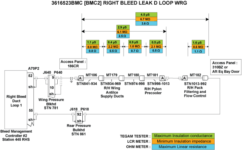
- Measure Insulation resistance and line resistance of the detection loops as per the Leak Detection Elements troubleshooting sheet. Make sure line resistance and insulation values are within the specified limits provided in image below.
- If the values are within specified limits, go to step 4.
- If values are not within the specified limits, continue with next step.
- Replace faulty elements.
- If system checks are good, do close out.
- If fault remains, continue with next step.
- Make sure the Leak Detection Elements are installed as per Bleed Air Leak Detection System - Maintenance Practices.
- If installation is not correct, rectify as required and do close out.
- If installation is good, continue with next step.
- Perform wiring checks of the remaining wires linking the right BLEED Loops circuit to BMC 2.
- If wiring checks are not good, repair defective wiring as required and do close out.
- If wiring checks are good, continue with next step.
NOTE: Inspect both ends of each loop to make sure the ceramic Inserts/Shield and Insert Assembly are not damaged. If repairs are necessary refer to CMM26-14-12.
- Interchange BMC 2 with BMC 1 to confirm the failure and replace if necessary.
NOTE: Refer to the Aft Equipment Bay Bleed Leak Troubleshooting Aid Reference Document for help in identifying leaks, component identification and tooling instructions. - Do the AMM task "36-11-61-790-801 - Leak Test of the UROSEAL Joints".
- Are results satisfactory?
- If YES, go to step 10.
- If NO, continue with next step.
- Do the AMM task "36-11-61-820-801 - Rigging of the UROSEALS".
- Is the OMS Fault cleared?
- If YES, do close out.
- If NO, continue with next step.
- Do the AMM task "36-11-00-790-801 - Leak Test of the Bleed Air System".
- Do close out.