

09/20/19
Message Overview:
Fault Message:
LOAD CONT VLV [LCV POSITION VS CMD]
Fault Code:
4960281APU
Associated CAS:
| Reporting LRU: | Full-Authority Digital Engine-Controller (FADEC) |
| System Description: | 49-60-00 |
| Schematic Diagram: | 49-61-00 [ Global Express ] [ G5000 ] [ Global XRS ] |
| Wiring Diagram: | 49-12-01 [ Global Express ] [ G5000 ] [ Global XRS ] 49-61-01 [ Global Express ] [ G5000 ] [ Global XRS ] |
Fault Description:
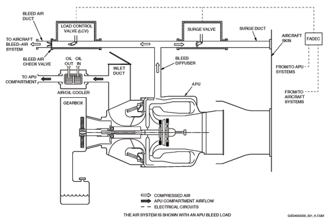
Full-Authority Digital Engine-Controller (FADEC) has detected that the Auxiliary Power Unit (APU) Load Control Valve (LCV) is not in the commanded position by more than 70 degress.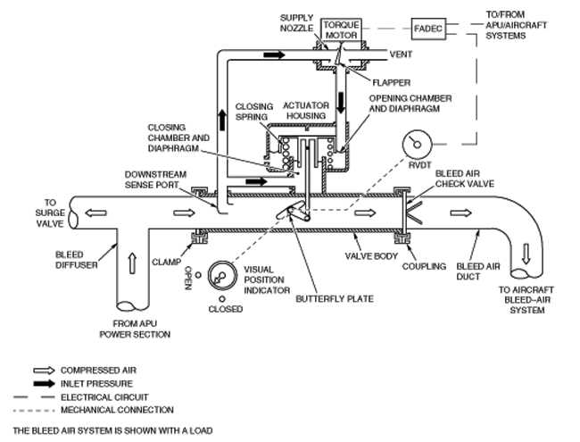
Possible Causes:
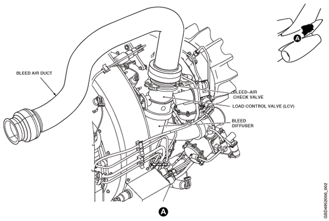
- Load Control Valve (LCV) (MPE1)
- Load-Control-Valve (LCV) Inlet Filter
- Load-Control-Valve (LCV) Torque Motor
- Auxiliary Power Unit (APU) Full-Authority Digital Engine-Controller (FADEC) (A108)
- Associated Wiring
Troubleshooting Tips:
Advisory Wire/Service Bulletin: None
Forum Articles/Infoservice/Newsletter:
- APU SIL-108 - Load Control Valve P/N 3291210-3 Filter Clean and Inspect
- APU SIL-143 - Introduction of a field cleaning procedure for the RE220[GX] Load Control Valve inlet filter Part No.361666-3
NOTE: If CAS message is not active, verify stored faults on CAIMS.
Quick Links:
| Access to Active Faults | AMM 45-45-00-970-802 [ Global Express ] [ G5000 ] [ Global XRS ] |
| Access to Stored Faults | AMM 45-45-00-970-803 [ Global Express ] [ G5000 ] [ Global XRS ] |
| Access to System Diagnostics | AMM 45-45-00-970-804 [ Global Express ] [ G5000 ] [ Global XRS ] |
| Operational Test of the Load Control Valve | AMM 49-50-00-710-801 [ Global Express ] [ G5000 ] [ Global XRS ] |
| Removal of the Load Control Valve | AMM 49-52-05-000-801 [ Global Express ] [ G5000 ] [ Global XRS ] |
| Installation of the Load Control Valve | AMM 49-52-05-400-801 [ Global Express ] [ G5000 ] [ Global XRS ] |
| Cleaning of the Load-Control-Valve Inlet Filter | AMM 49-52-05-160-801 [ Global Express ] [ G5000 ] [ Global XRS ] |
| Removal of the Full-Authority Digital Engine-Controller (FADEC) |
AMM 49-61-01-000-801 [ Global Express ] [ G5000 ] [ Global XRS ] |
| Installation of the Full-Authority Digital Engine-Controller (FADEC) |
AMM 49-61-01-400-801 [ Global Express ] [ G5000 ] [ Global XRS ] |
| Wire Repair - Maintenance Practices - ALL | SPM 20-12-10-02 [ Global Express ] [ G5000 ] [ Global XRS ] |
Troubleshooting Recommendations:
- Remove, inspect, clean and reinstall the LCV inlet filter.
- Visually Inspect wiring from LCV into APU Harness for any obvious signs of damage, while in the area.
- If system checks are not good, repair defective wiring as required and do close out.
- If system checks are good, continue with next step.
- Perform the operational test of the LCV.
- Re-rack FADEC and verify pin A108AP1-A9, A108AP1-A10, A108AP1-B9, A108AP1-B10, A108AP1-C9, A108AP1-J1 and A108AP1-K1 for damage or FOD, verify if fault is still present.
- If NO, do close out.
- If YES, continue with next step.
- Perform wiring checks between APU FADEC and load control valve connector (MPE1P1).
- If wiring checks are not good, repair defective wiring as required and do close out.
- If wiring checks are good, continue with next step.
- Replace load control valve.
- If system checks are good, do close out.
- If fault remains, continue with next step.
- Replace FADEC.
- Do close out.