

07/09/19
Message Overview:
Fault Message:
LANDING GEAR ECU [CH 2]/BUS FAULT
Fault Code:
27660232SX
Associated CAS:
| Reporting LRU: | Flight Control Unit (FCU) 2 |
| System Description: | 27-60-00 |
| Schematic Diagram: | 27-60-00 [ Global Express ] [ G5000 ] [ Global XRS ] 32-31-00 [ Global Express ] [ G5000 ] [ Global XRS ] |
| Wiring Diagram: | 27-60-02 [ Global Express ] [ G5000 ] [ Global XRS ] 32-31-05 [ Global Express ] [ G5000 ] [ Global XRS ] |
Fault Description:
There is a failure of the ARINC 429 data transmission to Flight Control Unit (FCU) 2.
Possible Causes:
- Landing Gear Electronic Control Unit (LGECU) (A52)
- Landing Gear Electronic Control Unit (LGECU) Channel B
- Data Acquisition Unit (DAU) 4 (A31)
- Junction Box (JB6)
- Junction Box (JB6)/PCB1
- Flight Control Unit (FCU) 2 (A66)
- Associated Wiring
Troubleshooting Tips:
Advisory Wire/Service Bulletin: None
Forum Articles/Infoservice/Newsletter: None
This fault may sometime be cleared by performing the flight control system reset procedure.
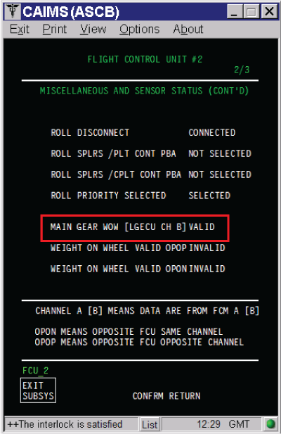
The status of the FCU can be found in CAIMS:
- SYSTEM DIAG
- 27-00 FLIGHT CONTROLS
- FLIGHT CONTROL UNIT #1
- LRU TEST
- DISPLAY MISC. & SENSORS STATUS
- Go to page 2 of 3
Quick Links:
| Removal of the Junction Box JB6 | AMM 24-00-13-000-801 [ Global Express ] [ G5000 ] [ Global XRS ] |
| Installation of the Junction Box JB6 | AMM 24-00-13-400-801 [ Global Express ] [ G5000 ] [ Global XRS ] |
| Removal of the Junction Box JB6 Circuit-Cards | AMM 24-00-14-000-801 [ Global Express ] [ G5000 ] [ Global XRS ] |
| Installation of the Junction Box JB6 Circuit-Cards | AMM 24-00-14-400-801 [ Global Express ] [ G5000 ] [ Global XRS ] |
| Removal of the Flight-Control Units | AMM 27-61-05-000-801 [ Global Express ] [ G5000 ] [ Global XRS ] |
| Installation of the Flight-Control Units | AMM 27-61-05-400-801 [ Global Express ] [ G5000 ] [ Global XRS ] |
| Removal of the Data Acquisition Units (DAU) | AMM 31-42-01-000-801 [ Global Express ] [ G5000 ] [ Global XRS ] |
| Installation of the Data Acquisition Units (DAU) | AMM 31-42-01-400-801 [ Global Express ] [ G5000 ] [ Global XRS ] |
| Removal of the Landing-Gear Electronic Control-Unit (LG ECU) | AMM 32-31-09-000-801 [ Global Express ] [ G5000 ] [ Global XRS ] |
| Installation of the Landing-Gear Electronic Control-Unit (LG ECU) | AMM 32-31-09-400-801 [ Global Express ] [ G5000 ] [ Global XRS ] |
| Access to Active Faults | AMM 45-45-00-970-802 [ Global Express ] [ G5000 ] [ Global XRS ] |
| Access to System Diagnostics | AMM 45-45-00-970-804 [ Global Express ] [ G5000 ] [ Global XRS ] |
| Electronic Junction Box | CMM 24-00-01 [ Global Express ] [ G5000] [ Global XRS ] |
| Wire Repair - Maintenance Practices - ALL | SPM 20-12-10-02 [ Global Express ] [ G5000 ] [ Global XRS ] |
Troubleshooting Recommendations:
- If the LGECU Channel B is reporting fault or is in red in CAIMS, start troubleshooting LGECU issue first.
NOTE: The LGECU has two channels, channel A and channel B. Channel A is also called CH 1 and channel B is also called CH 2 in this procedure. - Get access to the DAU 4 Active fault. If a fault, related to the LGECU, is reported, troubleshoot it first.
- Measure for 4.4 VDC or higher at JB6 test points for ARINC 429 Bus as follows:
ARINC 429 Bus For 93 pins Test point Connector
(JB6 PCB1 P/N 00514-0120-0002)JB6 (JB6DP1) FCU 2 DAU 4 LGECU High TP-77 JB6DP1-11B, JB6DP1-11D
and JB6DP1-11FA66AP1-9D A31CP1-D3 A52BP1-D4 Low TP-76 JB6DP1-11C, JB6DP1-11E
and JB6DP1-11GA66AP1-9C A31CP1-E3 A52BP1-D5 ARINC 429 Bus For 96 pins Test point Connector
(JB6 PCB1 P/N 00514-0120-0001)JB6 (JB6DP1) FCU 2 DAU 4 LGECU High TP-79 JB6DP1-11B, JB6DP1-11D
and JB6DP1-11FA66AP1-9D A31CP1-D3 A52BP1-D4 Low TP-78 JB6DP1-11C, JB6DP1-11E
and JB6DP1-11GA66AP1-9C A31CP1-E3 A52BP1-D5 - If voltage is not present, go to step 8.
- If voltage is present, continue with next step.
NOTE: The test point’s references inside the junction boxes in the wiring diagram are not accurate. (Reference CMM 24-00-01).
NOTE: Pin to pin and pin to ground wiring check can be done through the JB test point. DO NOT perform an insulation test through the junction box.
- Measure for 4.4 VDC or higher at FCU 2 for ARINC 429 Bus.
- If voltage is present, go to step 10.
- If voltage is not present, continue with next step.
- Perform wiring checks between FCU 2 and JB6 test points.
- If wiring checks are not good, repair defective wiring as required and do close out.
- If wiring checks are good, continue with next step.
- Replace JB6 Circuit Board 1 (JB6 PCB1).
- If system checks are good, do close out.
- If fault remains, continue with next step.
- Replace JB6.
- If system checks are good, do close out.
- If fault remains, continue with next step.
- Measure for 4.4 VDC or higher at DAU 4 for ARINC 429 Bus.
- If voltage is present, go to step 6.
- If voltage is not present, continue with next step.
- Measure for short circuit for shorted to ground, shorted to shield, and shorted between wires of ARINC 429 Bus.
- If system checks are good, do close out.
- If fault remains, continue with next step.
NOTE: Remove DAU 4, LGECU and FCU 2 for this test.
- Swap FCU 2 with FCU 1.
- If system checks are good, replace FCU 2. Reset FCUs latched faults and do close out.
- If fault remains, continue with next step.
- Swap DAU 4 with DAU 3.
- If system checks are good, replace DAU 4 and do close out.
- If fault remains, continue with next step.
- Re-rack LGECU.
- If system checks are good, do close out.
- If fault remains, continue with next step.
- Perform wiring checks between LGECU and JB6 test points for ARINC 429 Bus.
- If wiring checks are not good, repair defective wiring as required and do close out.
- If wiring checks are good, continue with next step.
- Replace LGECU.
- Do close out.